Configuration
3.7 Algorithm Set Up Group
Introduction
This data deals with various algorithms in the controller and Timer functions.
The Timer section allows you to configure a
Alarm 1 is activated at the end of the
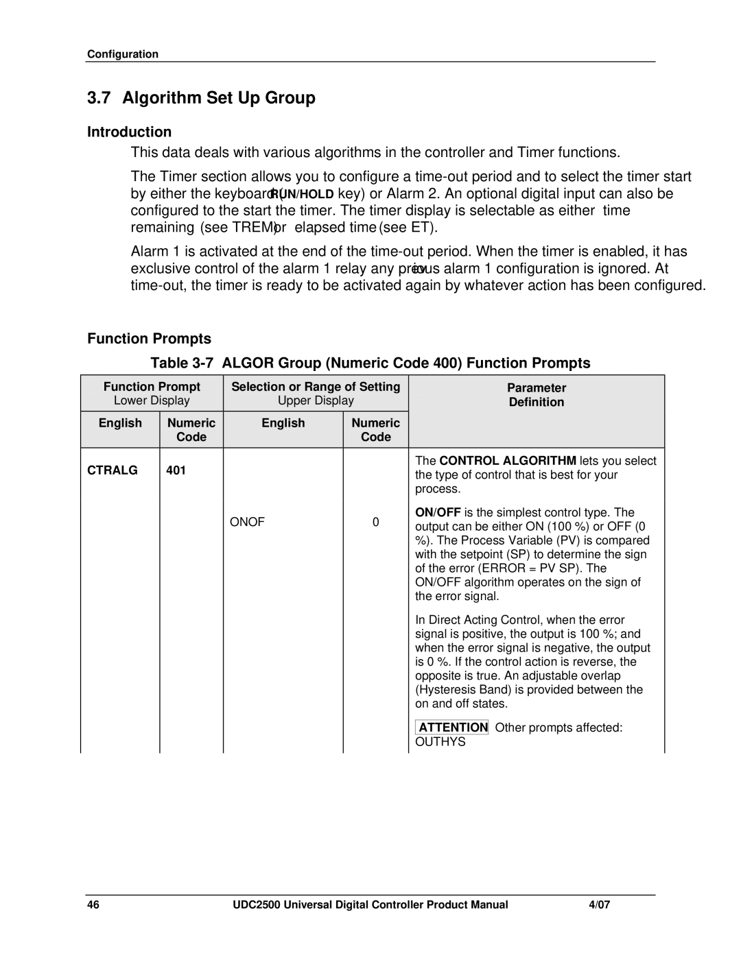
Function Prompts
Table
| Function Prompt |
| Selection or Range of Setting |
|
| Parameter | ||||
| Lower Display |
| Upper Display |
|
| Definition | ||||
| English | Numeric |
|
| English | Numeric |
|
|
|
|
|
| Code |
|
|
| Code |
|
|
|
|
| CTRALG | 401 |
|
|
|
|
|
| The CONTROL ALGORITHM lets you select | |
|
|
|
|
|
|
| the type of control that is best for your | |||
|
|
|
|
|
|
|
|
| process. | |
|
|
|
|
| ONOF | 0 |
|
| ON/OFF is the simplest control type. The | |
|
|
|
|
|
|
| output can be either ON (100 %) or OFF (0 | |||
|
|
|
|
|
|
|
|
| %). The Process Variable (PV) is compared | |
|
|
|
|
|
|
|
|
| with the setpoint (SP) to determine the sign | |
|
|
|
|
|
|
|
|
| of the error (ERROR = | |
|
|
|
|
|
|
|
|
| ON/OFF algorithm operates on the sign of | |
|
|
|
|
|
|
|
|
| the error signal. | |
|
|
|
|
|
|
|
|
| In Direct Acting Control, when the error | |
|
|
|
|
|
|
|
|
| signal is positive, the output is 100 %; and | |
|
|
|
|
|
|
|
|
| when the error signal is negative, the output | |
|
|
|
|
|
|
|
|
| is 0 %. If the control action is reverse, the | |
|
|
|
|
|
|
|
|
| opposite is true. An adjustable overlap | |
|
|
|
|
|
|
|
|
| (Hysteresis Band) is provided between the | |
|
|
|
|
|
|
|
|
| on and off states. | |
|
|
|
|
|
|
|
|
|
| Other prompts affected: |
|
|
|
|
|
|
|
|
| ATTENTION | |
|
|
|
|
|
|
|
|
| OUTHYS |
|
|
|
|
|
|
|
|
|
|
|
|
46 | UDC2500 Universal Digital Controller Product Manual | 4/07 |