Installation
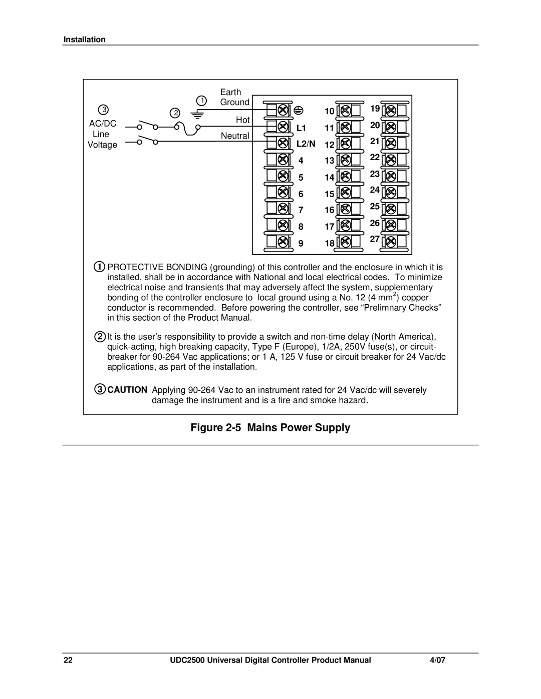
| 1 | Earth |
|
|
3 | Ground | 10 | 19 | |
2 | Hot | |||
AC/DC |
| 11 | 20 | |
| L1 | |||
Line |
| Neutral | 12 | 21 |
Voltage |
| L2/N | ||
|
| 4 | 13 | 22 |
|
|
| ||
|
| 5 | 14 | 23 |
|
|
| ||
|
| 6 | 15 | 24 |
|
|
| ||
|
| 7 | 16 | 25 |
|
|
| ||
|
| 8 | 17 | 26 |
|
|
| ||
|
| 9 | 18 | 27 |
|
|
|
1PROTECTIVE BONDING (grounding) of this controller and the enclosure in which it is installed, shall be in accordance with National and local electrical codes. To minimize electrical noise and transients that may adversely affect the system, supplementary bonding of the controller enclosure to local ground using a No. 12 (4 mm2) copper conductor is recommended. Before powering the controller, see “Prelimnary Checks” in this section of the Product Manual.
2It is the user’s responsibility to provide a switch and
3CAUTION Applying
Figure 2-5 Mains Power Supply
22 | UDC2500 Universal Digital Controller Product Manual | 4/07 |