Configuration
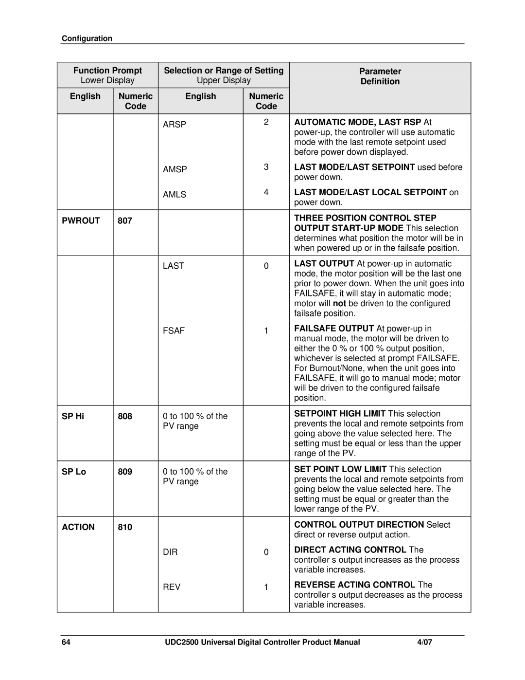
Function Prompt | Selection or Range of Setting | Parameter | ||
Lower Display | Upper Display | Definition | ||
English | Numeric | English | Numeric |
|
| Code |
| Code |
|
|
| ARSP | 2 | AUTOMATIC MODE, LAST |
|
|
|
| |
|
|
|
| mode with the last remote setpoint used |
|
|
|
| before power down displayed. |
|
| AMSP | 3 | LAST MODE/LAST SETPOINT used before |
|
|
|
| power down. |
|
| AMLS | 4 | LAST MODE/LAST LOCAL SETPOINT on |
|
|
|
| power down. |
PWROUT | 807 |
|
| THREE POSITION CONTROL STEP |
|
|
|
| OUTPUT |
|
|
|
| determines what position the motor will be in |
|
|
|
| when powered up or in the failsafe position. |
|
| LAST | 0 | LAST |
|
|
|
| mode, the motor position will be the last one |
|
|
|
| prior to power down. When the unit goes into |
|
|
|
| FAILSAFE, it will stay in automatic mode; |
|
|
|
| motor will not be driven to the configured |
|
|
|
| failsafe position. |
|
| FSAF | 1 | FAILSAFE |
|
|
|
| manual mode, the motor will be driven to |
|
|
|
| either the 0 % or 100 % output position, |
|
|
|
| whichever is selected at prompt FAILSAFE. |
|
|
|
| For Burnout/None, when the unit goes into |
|
|
|
| FAILSAFE, it will go to manual mode; motor |
|
|
|
| will be driven to the configured failsafe |
|
|
|
| position. |
|
|
|
|
|
SP Hi | 808 | 0 to 100 % of the |
| SETPOINT HIGH |
|
| PV range |
| prevents the local and remote setpoints from |
|
|
|
| going above the value selected here. The |
|
|
|
| setting must be equal or less than the upper |
|
|
|
| range of the PV. |
SP Lo | 809 | 0 to 100 % of the |
| SET POINT LOW |
|
| PV range |
| prevents the local and remote setpoints from |
|
|
|
| going below the value selected here. The |
|
|
|
| setting must be equal or greater than the |
|
|
|
| lower range of the PV. |
ACTION | 810 |
|
| CONTROL OUTPUT |
|
|
|
| direct or reverse output action. |
|
| DIR | 0 | DIRECT ACTING |
|
|
|
| controller’s output increases as the process |
|
|
|
| variable increases. |
|
| REV | 1 | REVERSE ACTING |
|
|
|
| controller’s output decreases as the process |
|
|
|
| variable increases. |
64 | UDC2500 Universal Digital Controller Product Manual | 4/07 |