Output Calibration
Procedure
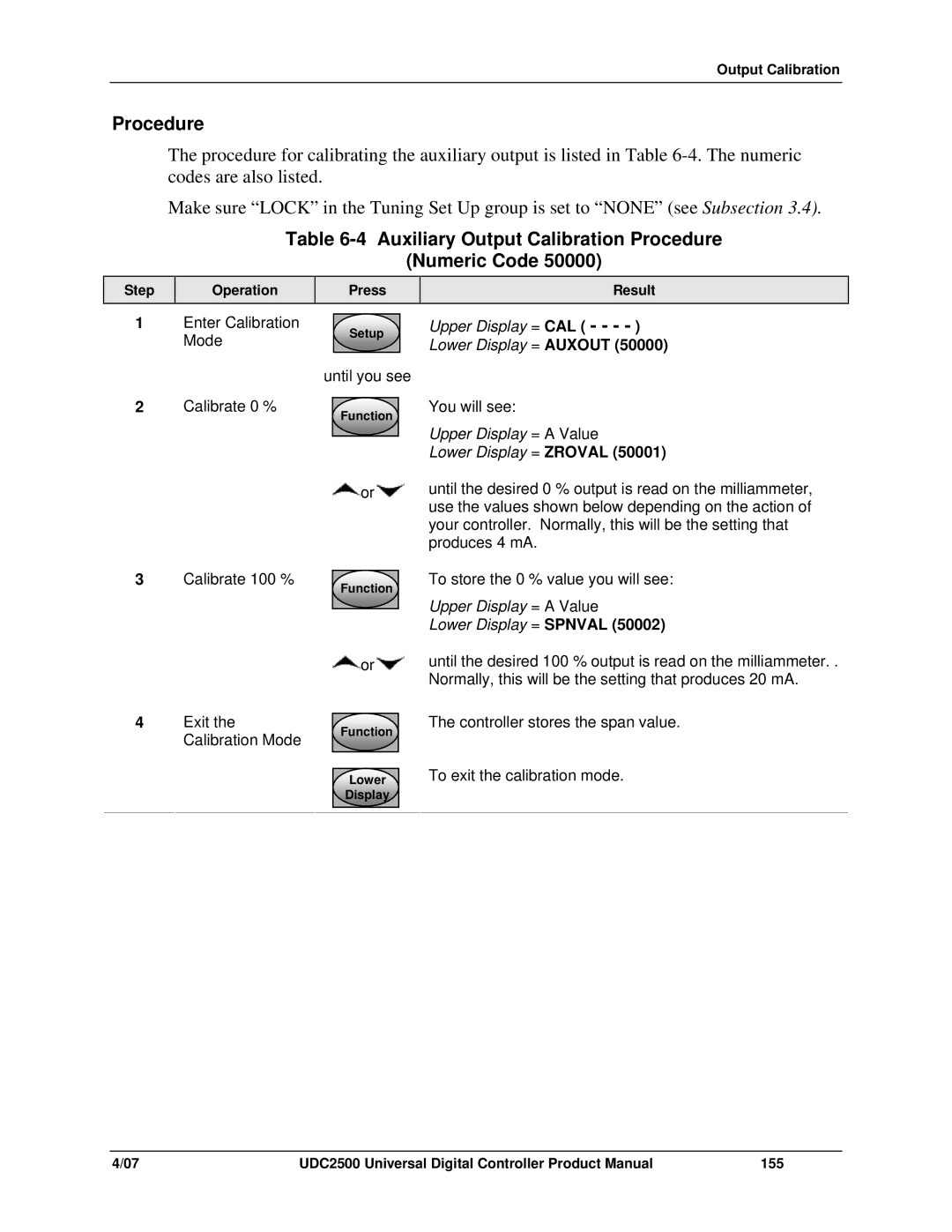
The procedure for calibrating the auxiliary output is listed in Table
Make sure “LOCK” in the Tuning Set Up group is set to “NONE” (see Subsection 3.4).
Table 6-4 Auxiliary Output Calibration Procedure
(Numeric Code 50000)
Step
Operation
Press
Result
1 | Enter Calibration |
| Setup |
| Upper Display = CAL ( - - - - ) |
| Mode |
|
|
| Lower Display = AUXOUT (50000) |
|
| until you see |
| ||
2 | Calibrate 0 % |
|
|
| You will see: |
| Function |
| |||
|
|
|
| Upper Display = A Value | |
|
|
|
|
| |
|
|
|
|
| |
|
|
|
|
| Lower Display = ZROVAL (50001) |
|
|
| or | until the desired 0 % output is read on the milliammeter, | |
use the values shown below depending on the action of your controller. Normally, this will be the setting that produces 4 mA.
3 | Calibrate 100 % | Function |
|
| |
|
| or |
4 | Exit the | Function |
| Calibration Mode | |
|
| |
|
| Lower |
|
| Display |
To store the 0 % value you will see:
Upper Display = A Value
Lower Display = SPNVAL (50002)
until the desired 100 % output is read on the milliammeter. . Normally, this will be the setting that produces 20 mA.
The controller stores the span value.
To exit the calibration mode.
4/07 | UDC2500 Universal Digital Controller Product Manual | 155 |