Installation
Table
UDC Terminal | UDC Signal Name | RJ45 Socket Pin # |
|
|
|
Position 14 | Shield | Shield |
|
|
|
Position 15 | RXD- | 6 |
|
|
|
Position 16 | RXD+ | 3 |
|
|
|
Position 17 | TXD- | 2 |
|
|
|
Position 18 | TXD+ | 1 |
|
|
|
Switch Signal
Name
Shield
TXD-
TXD+
RXD-
RXD+
Table
Table
through cable
UDC Terminal | UDC Signal Name | RJ45 Socket Pin # |
Position 14 | Shield | Shield |
|
|
|
Position 15 | RXD- | 2 |
|
|
|
Position 16 | RXD+ | 1 |
|
|
|
Position 17 | TXD- | 6 |
|
|
|
Position 18 | TXD+ | 3 |
|
|
|
PC Signal Name
Shield
TXD-
TXD+
RXD-
RXD+
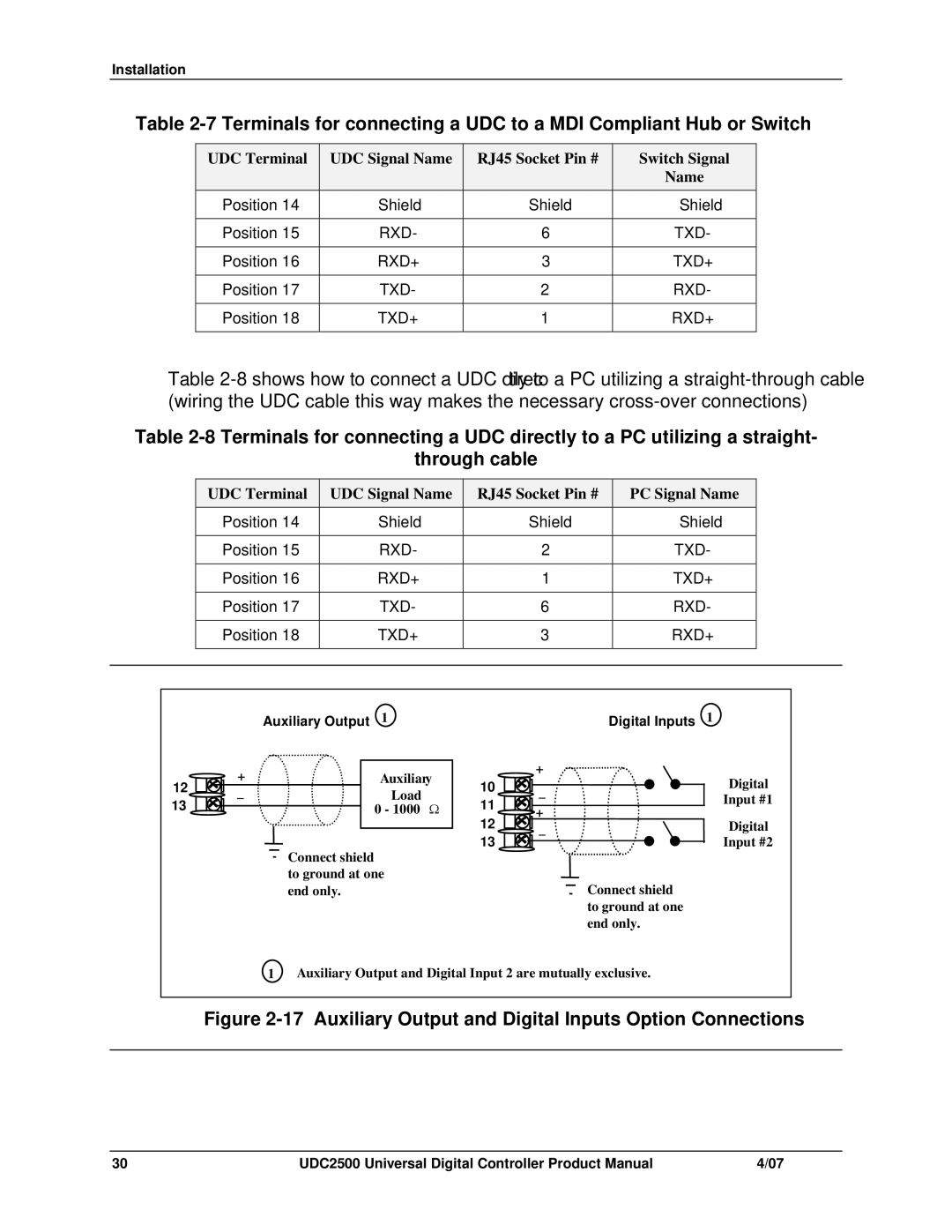
Auxiliary Output 1 | Digital Inputs 1 |
12 | + | Auxiliary |
_ | Load | |
13 |
| 0 - 1000 Ω |
![]() Connect shield to ground at one end only.
Connect shield to ground at one end only.
| + | |
10 | _ | |
11 | + | |
12 | ||
_ | ||
13 |
|
Connect shield to ground at one end only.
Digital
Input #1
Digital
Input #2
1 Auxiliary Output and Digital Input 2 are mutually exclusive.
Figure 2-17 Auxiliary Output and Digital Inputs Option Connections
30 | UDC2500 Universal Digital Controller Product Manual | 4/07 |