Input Calibration
Table 5-2 Voltage and Milliamp Equivalents for Input 2 Range Values
Sensor Type | PV Input Range | |
|
|
|
Linear |
|
|
Milliamps | 4 to 20 mA | |
| 0 to 20 mA | |
Volts | 1 to | 5 Volts |
| 0 to | 5 Volts |
| 0 to | 2 Volts |
|
|
|
Range Values
0 % | 100 % |
|
4.00 mA | 20.00 mA |
|
0.00 mA | 20.00 mA |
|
1.00 Volts | 5.00 Volts |
|
0.00 Volts | 5.00 Volts |
|
0.00 Volts | 2.00 Volts |
|
|
|
|
5.3 Preliminary Information
Disconnect the Field Wiring
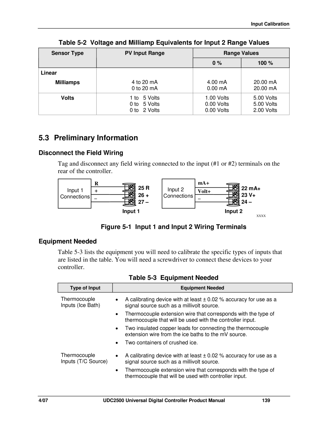
Tag and disconnect any field wiring connected to the input (#1 or #2) terminals on the rear of the controller.
Input 1
Connections
R | 25 R | |
+ | ||
26 + | ||
_ | ||
| 27 – |
Input 1
Input 2
Connections
mA+ | 22 mA+ | |
Volt+ | ||
23 V+ | ||
_ | ||
| 24 – |
Input 2
XXXX
Figure 5-1 Input 1 and Input 2 Wiring Terminals
Equipment Needed
Table
Table
Type of Input
Equipment Needed
Thermocouple Inputs (Ice Bath)
•A calibrating device with at least ± 0.02 % accuracy for use as a signal source such as a millivolt source.
•Thermocouple extension wire that corresponds with the type of thermocouple that will be used with the controller input.
•Two insulated copper leads for connecting the thermocouple extension wire from the ice baths to the mV source.
•Two containers of crushed ice.
Thermocouple Inputs (T/C Source)
•A calibrating device with at least ± 0.02 % accuracy for use as a signal source such as a millivolt source.
•Thermocouple extension wire that corresponds with the type of thermocouple that will be used with controller input.
4/07 | UDC2500 Universal Digital Controller Product Manual | 139 |