Configuration
Function Prompt |
| Selection or Range of Setting |
|
| Parameter | |||
Lower Display |
| Upper Display |
|
| Definition | |||
English | Numeric |
| English | Numeric |
|
|
|
|
| Code |
|
| Code |
|
|
|
|
|
|
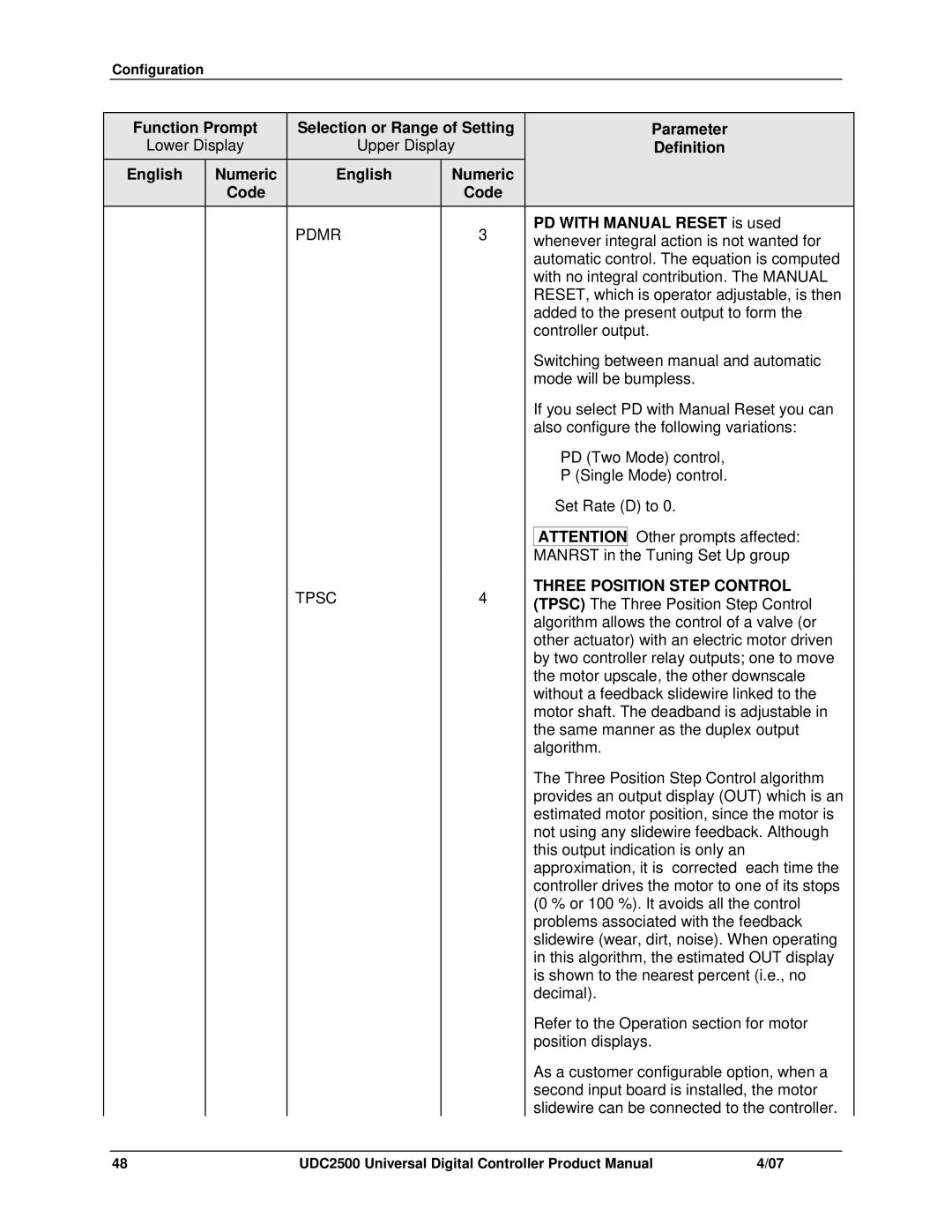
| PDMR | 3 |
|
| PD WITH MANUAL RESET is used | |
|
|
|
|
| whenever integral action is not wanted for | |||
|
|
|
|
|
|
| automatic control. The equation is computed | |
|
|
|
|
|
|
| with no integral contribution. The MANUAL | |
|
|
|
|
|
|
| RESET, which is operator adjustable, is then | |
|
|
|
|
|
|
| added to the present output to form the | |
|
|
|
|
|
|
| controller output. | |
|
|
|
|
|
|
| Switching between manual and automatic | |
|
|
|
|
|
|
| mode will be bumpless. | |
|
|
|
|
|
|
| If you select PD with Manual Reset you can | |
|
|
|
|
|
|
| also configure the following variations: | |
|
|
|
|
|
|
| • PD (Two Mode) control, | |
|
|
|
|
|
|
| • P (Single Mode) control. | |
|
|
|
|
|
|
| • Set Rate (D) to 0. | |
|
|
|
|
|
|
|
| Other prompts affected: |
|
|
|
|
|
|
| ATTENTION | |
|
|
|
|
|
|
| MANRST in the Tuning Set Up group | |
|
|
| TPSC | 4 |
|
| THREE POSITION STEP CONTROL | |
|
|
|
|
| ||||
|
|
|
|
|
|
| ||
|
|
|
|
|
|
| algorithm allows the control of a valve (or | |
|
|
|
|
|
|
| other actuator) with an electric motor driven | |
|
|
|
|
|
|
| by two controller relay outputs; one to move | |
|
|
|
|
|
|
| the motor upscale, the other downscale | |
|
|
|
|
|
|
| without a feedback slidewire linked to the | |
|
|
|
|
|
|
| motor shaft. The deadband is adjustable in | |
|
|
|
|
|
|
| the same manner as the duplex output | |
|
|
|
|
|
|
| algorithm. | |
|
|
|
|
|
|
| The Three Position Step Control algorithm | |
|
|
|
|
|
|
| provides an output display (OUT) which is an | |
|
|
|
|
|
|
| estimated motor position, since the motor is | |
|
|
|
|
|
|
| not using any slidewire feedback. Although | |
|
|
|
|
|
|
| this output indication is only an | |
|
|
|
|
|
|
| approximation, it is “corrected” each time the | |
|
|
|
|
|
|
| controller drives the motor to one of its stops | |
|
|
|
|
|
|
| (0 % or 100 %). It avoids all the control | |
|
|
|
|
|
|
| problems associated with the feedback | |
|
|
|
|
|
|
| slidewire (wear, dirt, noise). When operating | |
|
|
|
|
|
|
| in this algorithm, the estimated OUT display | |
|
|
|
|
|
|
| is shown to the nearest percent (i.e., no | |
|
|
|
|
|
|
| decimal). | |
|
|
|
|
|
|
| Refer to the Operation section for motor | |
|
|
|
|
|
|
| position displays. | |
|
|
|
|
|
|
| As a customer configurable option, when a | |
|
|
|
|
|
|
| second input board is installed, the motor | |
|
|
|
|
|
|
| slidewire can be connected to the controller. | |
48 | UDC2500 Universal Digital Controller Product Manual | 4/07 |