Monitoring and Operating the Controller
4.17 Setting Failsafe Mode
Introduction
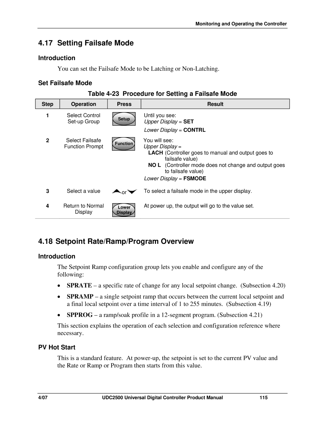
You can set the Failsafe Mode to be Latching or
Set Failsafe Mode
Table 4-23 Procedure for Setting a Failsafe Mode
Step
Operation
Press
Result
1Select Control
2Select Failsafe
Function Prompt
Setup
Function
Until you see:
Upper Display = SET
Lower Display = CONTRL
You will see: Upper Display =
LACH (Controller goes to manual and output goes to failsafe value)
NO L (Controller mode does not change and output goes to failsafe value)
Lower Display = FSMODE
3 | Select a value | or | To select a failsafe mode in the upper display. |
4 | Return to Normal |
| At power up, the output will go to the value set. |
Lower | |||
| Display | Display |
|
|
|
|
|
4.18 Setpoint Rate/Ramp/Program Overview
Introduction
The Setpoint Ramp configuration group lets you enable and configure any of the following:
•SPRATE – a specific rate of change for any local setpoint change. (Subsection 4.20)
•SPRAMP – a single setpoint ramp that occurs between the current local setpoint and a final local setpoint over a time interval of 1 to 255 minutes. (Subsection 4.19)
•SPPROG – a ramp/soak profile in a
This section explains the operation of each selection and configuration reference where necessary.
PV Hot Start
This is a standard feature. At
4/07 | UDC2500 Universal Digital Controller Product Manual | 115 |
