Input Calibration
Type of Input
Equipment Needed
RTD (Resistance
Thermometer
Device)
Milliampere,
Millivolt, Volts, and
Radiamatic
•A decade box, with at least ± 0.02 % accuracy, capable of providing stepped resistance values over a minimum range of 0 to 1650 ohms with a resolution of 0.001 ohm.
•Three insulated copper leads of equal length for connecting the decade box to the controller.
•A calibrating device with at least ± 0.02 % accuracy for use as a signal source.
•Two insulated copper leads for connecting the calibrator to the controller.
•Place current source at zero before switching ON.
•Do not switch current sources OFF/ON while connected to the UDC2500 input.
5.4 Input 1 Set Up Wiring
Thermocouple Inputs Using an Ice Bath
Refer to Figure
Table
Using an Ice Bath
Step | Action |
|
|
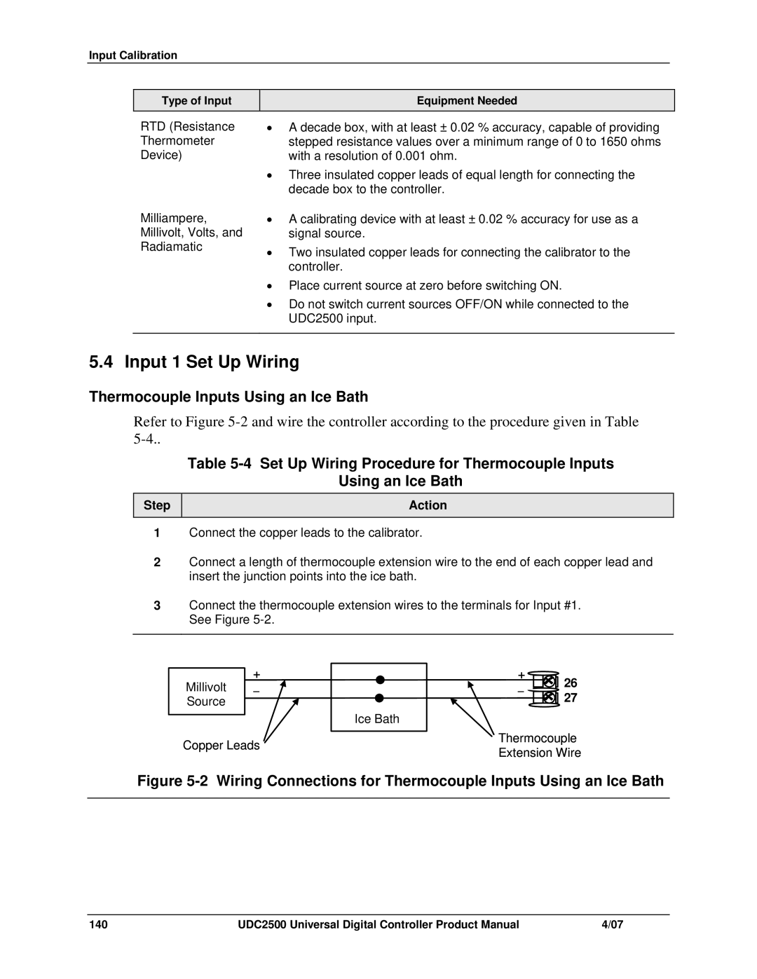
1Connect the copper leads to the calibrator.
2Connect a length of thermocouple extension wire to the end of each copper lead and insert the junction points into the ice bath.
3Connect the thermocouple extension wires to the terminals for Input #1. See Figure
+
Millivolt _ Source
Copper Leads
Ice Bath
+ | 26 |
_ | |
| 27 |
Thermocouple
Extension Wire
Figure 5-2 Wiring Connections for Thermocouple Inputs Using an Ice Bath
140 | UDC2500 Universal Digital Controller Product Manual | 4/07 |