Output Calibration
6.4 Restore Output Factory Calibration Procedure
Introduction
The factory calibration constants for the Current and Auxiliary Outputs are stored in its
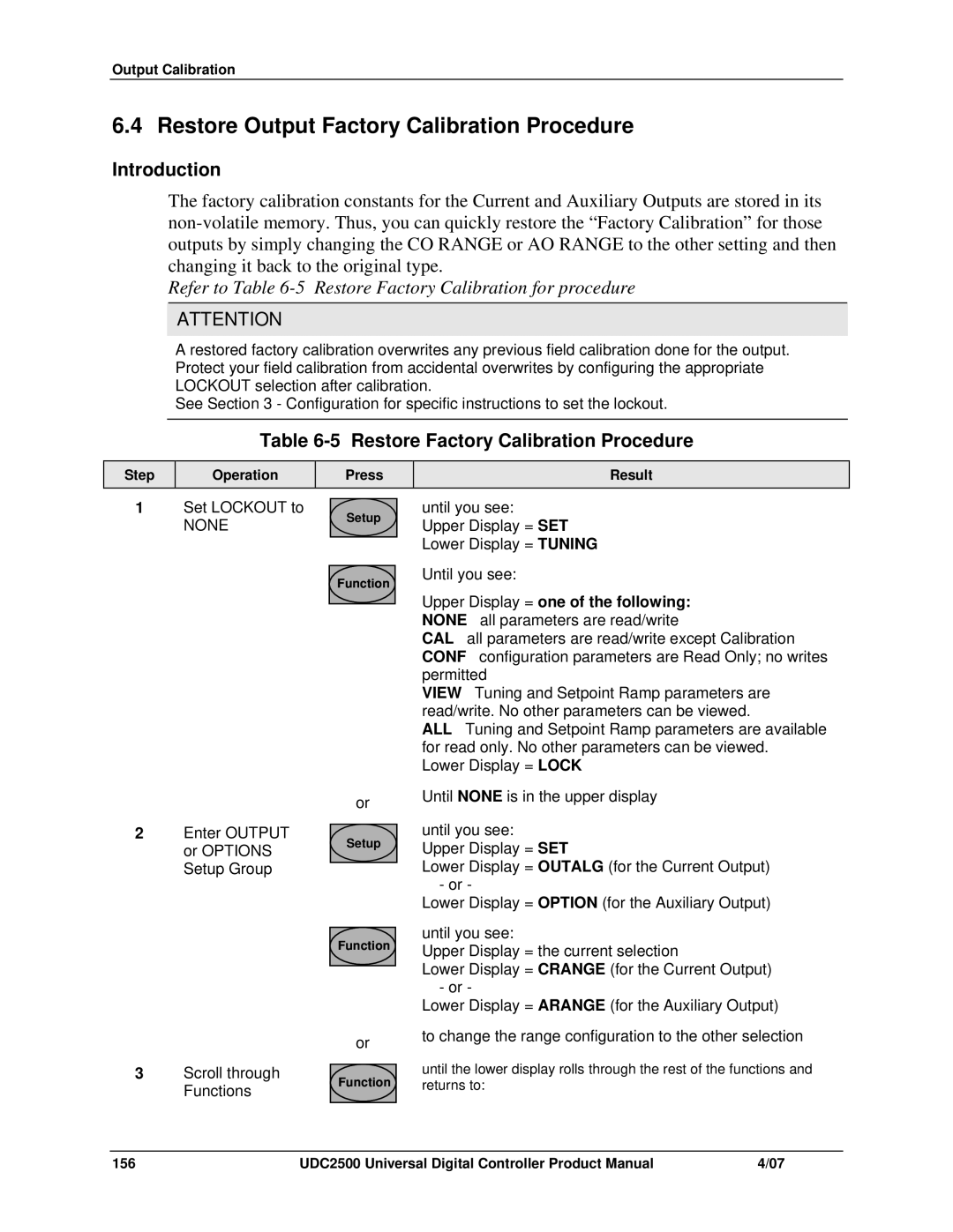
Refer to Table 6-5 Restore Factory Calibration for procedure
ATTENTION
A restored factory calibration overwrites any previous field calibration done for the output. Protect your field calibration from accidental overwrites by configuring the appropriate LOCKOUT selection after calibration.
See Section 3 - Configuration for specific instructions to set the lockout.
Table 6-5 Restore Factory Calibration Procedure
Step
Operation
Press
Result
1Set LOCKOUT to
NONE
Setup
until you see:
Upper Display = SET Lower Display = TUNING
Function
Until you see:
Upper Display = one of the following: NONE – all parameters are read/write
CAL – all parameters are read/write except Calibration CONF – configuration parameters are Read Only; no writes permitted
VIEW – Tuning and Setpoint Ramp parameters are read/write. No other parameters can be viewed.
ALL – Tuning and Setpoint Ramp parameters are available for read only. No other parameters can be viewed.
Lower Display = LOCK
|
| or | |
2 | Enter OUTPUT |
| |
Setup | |||
| or OPTIONS | ||
|
| ||
| Setup Group |
|
Function
|
| or |
3 | Scroll through | Function |
| Functions | |
|
|
Until NONE is in the upper display
until you see:
Upper Display = SET
Lower Display = OUTALG (for the Current Output) - or -
Lower Display = OPTION (for the Auxiliary Output)
until you see:
Upper Display = the current selection
Lower Display = CRANGE (for the Current Output) - or -
Lower Display = ARANGE (for the Auxiliary Output)
to change the range configuration to the other selection
until the lower display rolls through the rest of the functions and returns to:
156 | UDC2500 Universal Digital Controller Product Manual | 4/07 |