Configuration
| Function Prompt |
| Selection or Range of Setting |
|
| Parameter | ||||
| Lower Display |
| Upper Display |
|
| Definition | ||||
| English | Numeric |
|
| English | Numeric |
|
|
|
|
|
| Code |
|
|
| Code |
|
|
|
|
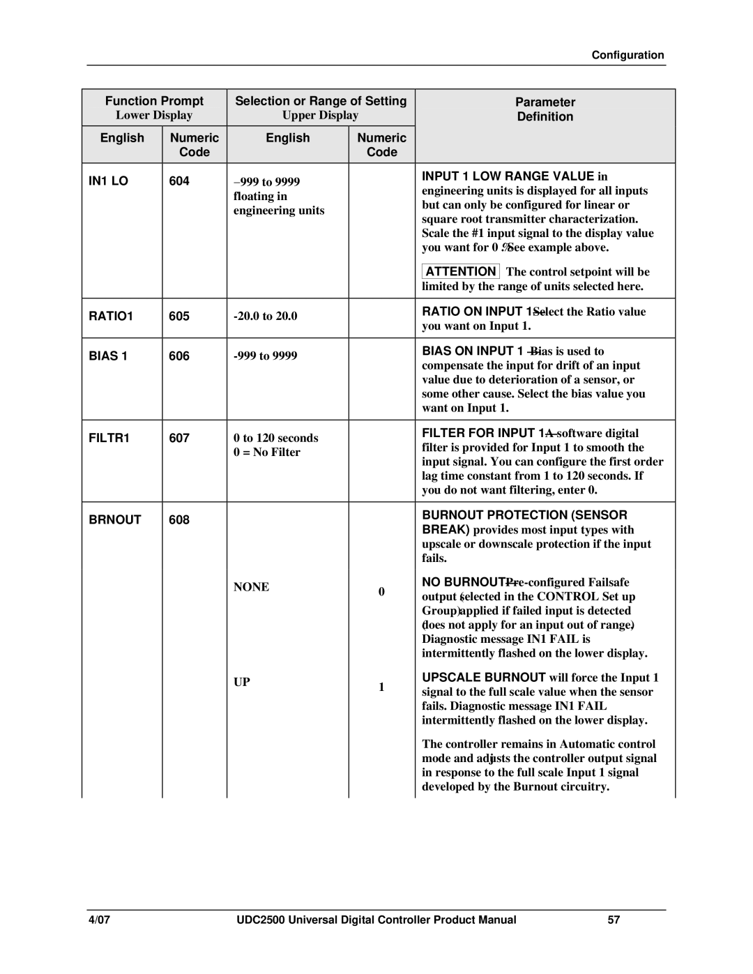
| IN1 LO | 604 |
|
| −999 to 9999 |
|
|
| INPUT 1 LOW RANGE VALUE in | |
|
|
|
|
|
| engineering units is displayed for all inputs | ||||
|
|
|
|
| floating in |
|
|
| ||
|
|
|
|
|
|
|
| but can only be configured for linear or | ||
|
|
|
|
| engineering units |
|
|
| ||
|
|
|
|
|
|
|
| square root transmitter characterization. | ||
|
|
|
|
|
|
|
|
| ||
|
|
|
|
|
|
|
|
| Scale the #1 input signal to the display value | |
|
|
|
|
|
|
|
|
| you want for 0 %. See example above. | |
|
|
|
|
|
|
|
|
|
| The control setpoint will be |
|
|
|
|
|
|
|
|
| ATTENTION | |
|
|
|
|
|
|
|
|
| limited by the | range of units selected here. |
|
|
|
|
|
|
|
|
|
| |
| RATIO1 | 605 |
|
|
|
|
| RATIO ON INPUT | ||
|
|
|
|
|
| you want on Input 1. | ||||
|
|
|
|
|
|
|
|
| ||
|
|
|
|
|
|
|
|
|
| |
| BIAS 1 | 606 |
|
|
|
|
| BIAS ON INPUT 1 — Bias is used to | ||
|
|
|
|
|
| compensate the input for drift of an input | ||||
|
|
|
|
|
|
|
|
| ||
|
|
|
|
|
|
|
|
| value due to deterioration of a sensor, or | |
|
|
|
|
|
|
|
|
| some other cause. Select the bias value you | |
|
|
|
|
|
|
|
|
| want on Input 1. | |
|
|
|
|
|
|
|
|
|
| |
| FILTR1 | 607 |
|
| 0 to 120 seconds |
|
|
| FILTER FOR INPUT | |
|
|
|
|
|
| filter is provided for Input 1 to smooth the | ||||
|
|
|
|
| 0 = No Filter |
|
|
| ||
|
|
|
|
|
|
|
| input signal. You can configure the first order | ||
|
|
|
|
|
|
|
|
| ||
|
|
|
|
|
|
|
|
| lag time constant from 1 to 120 seconds. If | |
|
|
|
|
|
|
|
|
| you do not want filtering, enter 0. | |
|
|
|
|
|
|
|
|
|
| |
| BRNOUT | 608 |
|
|
|
|
|
| BURNOUT PROTECTION (SENSOR | |
|
|
|
|
|
|
| BREAK) provides most input types with | |||
|
|
|
|
|
|
|
|
| ||
|
|
|
|
|
|
|
|
| upscale or downscale protection if the input | |
|
|
|
|
|
|
|
|
| fails. | |
|
|
|
|
| NONE | 0 |
|
| NO | |
|
|
|
|
|
|
|
| output (selected in the CONTROL Set up | ||
|
|
|
|
|
|
|
|
| Group) applied if failed input is detected | |
|
|
|
|
|
|
|
|
| (does not apply for an input out of range). | |
|
|
|
|
|
|
|
|
| Diagnostic message IN1 FAIL is | |
|
|
|
|
|
|
|
|
| intermittently flashed on the lower display. | |
|
|
|
|
| UP | 1 |
|
| UPSCALE BURNOUT will force the Input 1 | |
|
|
|
|
|
|
|
| signal to the full scale value when the sensor | ||
|
|
|
|
|
|
|
|
| fails. Diagnostic message IN1 FAIL | |
|
|
|
|
|
|
|
|
| intermittently flashed on the lower display. | |
|
|
|
|
|
|
|
|
| The controller remains in Automatic control | |
|
|
|
|
|
|
|
|
| mode and adjusts the controller output signal | |
|
|
|
|
|
|
|
|
| in response to the full scale Input 1 signal | |
|
|
|
|
|
|
|
|
| developed by the Burnout circuitry. | |
|
|
|
|
|
|
|
|
|
|
|
4/07 | UDC2500 Universal Digital Controller Product Manual | 57 |