Monitoring and Operating the Controller
4.5.3 Diagnostic Messages
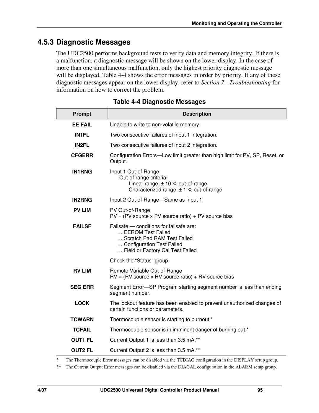
The UDC2500 performs background tests to verify data and memory integrity. If there is a malfunction, a diagnostic message will be shown on the lower display. In the case of more than one simultaneous malfunction, only the highest priority diagnostic message will be displayed. Table
Table 4-4 Diagnostic Messages
Prompt | Description |
|
|
EEFAIL Unable to write to
IN1FL | Two consecutive failures of input 1 integration. |
IN2FL | Two consecutive failures of input 2 integration. |
CFGERR | Configuration |
| Output. |
IN1RNG | Input 1 |
| |
| Linear range: ± 10 % |
| Characterized range: ± 1 % |
IN2RNG | Input 2 |
PV LIM | PV |
| PV = (PV source x PV source ratio) + PV source bias |
FAILSF | Failsafe — conditions for failsafe are: |
| … EEROM Test Failed |
| … Scratch Pad RAM Test Failed |
| … Configuration Test Failed |
| … Field or Factory Cal Test Failed |
| Check the “Status” group. |
RV LIM | Remote Variable |
| RV = (RV source x RV source ratio) + RV source bias |
SEG ERR | Segment |
| segment number. |
LOCK | The lockout feature has been enabled to prevent unauthorized changes of |
| certain functions or parameters. |
TCWARN | Thermocouple sensor is starting to burnout.* |
TCFAIL | Thermocouple sensor is in imminent danger of burning out.* |
OUT1 FL | Current Output 1 is less than 3.5 mA.** |
OUT2 FL | Current Output 2 is less than 3.5 mA.** |
*The Thermocouple Error messages can be disabled via the TCDIAG configuration in the DISPLAY setup group.
**The Current Output Error messages can be disabled via the DIAGAL configuration in the ALARM setup group.
4/07 | UDC2500 Universal Digital Controller Product Manual | 95 |