Installation
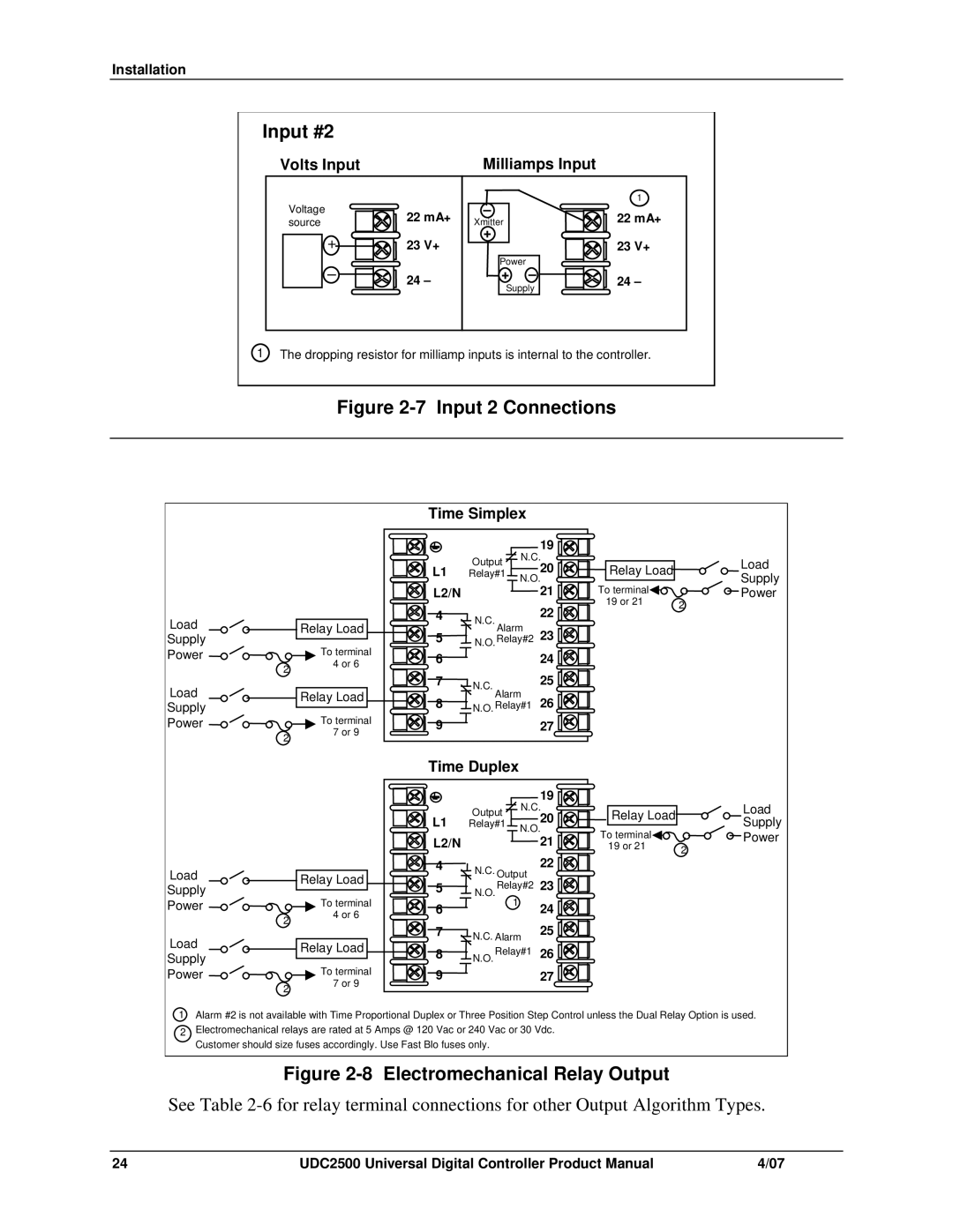
Input #2
Volts Input | Milliamps Input |
Voltage source
+
–
22mA+
23V+
24–
–
Xmitter
+
Power
+ –
Supply
1
22mA+
23V+
24–
1 The dropping resistor for milliamp inputs is internal to the controller.
Figure 2-7 Input 2 Connections
|
|
| Time Simplex |
| ||
|
|
|
|
|
| 19 |
|
|
|
| Output | N.C. | |
|
|
| L1 |
| 20 | |
|
|
| Relay#1 | N.O | ||
|
|
| L2/N |
| 21 | |
|
|
|
|
| ||
Load |
| Relay Load | 4 | N.C. Alarm | 22 | |
| 5 | 23 | ||||
Supply |
| To terminal | N.O.Relay#2 | |||
Power |
| 6 |
|
| 24 | |
2 | 4 or 6 |
|
| |||
|
| 7 |
|
| 25 | |
Load |
| Relay Load | N.C. Alarm | |||
| 8 | 26 | ||||
Supply |
| To terminal | N.O. Relay#1 | |||
Power |
| 9 |
|
| 27 | |
2 | 7 or 9 |
|
| |||
|
|
|
|
| ||
|
|
|
|
|
| |
Relay Load | Load | |
Supply | ||
|
To terminal | Power |
19 or 21 | 2 |
|
|
|
| Time Duplex |
|
| |
|
|
|
|
|
| 19 |
|
|
|
| Output | N.C. | |
|
|
| L1 |
| 20 | |
|
|
| Relay#1 |
| ||
|
|
| N.O. | |||
|
|
| L2/N |
|
| 21 |
Load |
| Relay Load | 4 | N.C. Output | 22 | |
|
| 23 | ||||
| 5 | N.O.Relay#2 | ||||
Supply |
| To terminal | ||||
Power |
| 6 | 1 |
| 24 | |
2 | 4 or 6 |
|
| |||
|
| 7 |
|
| 25 | |
Load |
| Relay Load | N.C. Alarm | |||
| 8 | N.O. Relay#1 | 26 | |||
Supply |
| To terminal | ||||
Power |
| 9 |
|
| 27 | |
2 | 7 or 9 |
|
| |||
|
|
|
|
| ||
|
|
|
|
|
| |
Relay Load | Load | |
Supply | ||
|
To terminal | Power |
19 or 21 | 2 |
|
1 Alarm #2 is not available with Time Proportional Duplex or Three Position Step Control unless the Dual Relay Option is used.
2Electromechanical relays are rated at 5 Amps @ 120 Vac or 240 Vac or 30 Vdc. Customer should size fuses accordingly. Use Fast Blo fuses only.
Figure 2-8 Electromechanical Relay Output
See Table
24 | UDC2500 Universal Digital Controller Product Manual | 4/07 |