Modbus Read, Write and Override Parameters plus Exception Codes
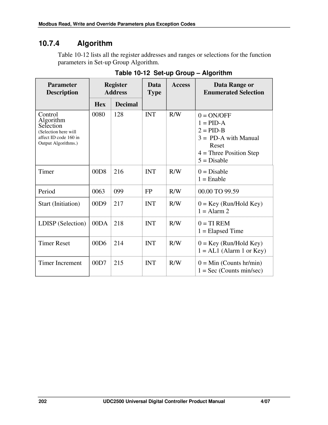
10.7.4Algorithm
Table
|
|
|
| Table | ||||||
| Parameter | Register | Data |
| Access |
| Data Range or | |||
| Description | Address | Type |
|
|
| Enumerated Selection | |||
|
| Hex |
| Decimal |
|
|
|
|
|
|
|
|
|
|
|
|
|
|
|
|
|
| Control | 0080 |
| 128 |
| INT |
| R/W | 0 | = ON/OFF |
| Algorithm |
|
|
|
|
|
|
| 1 | = |
| Selection |
|
|
|
|
|
|
| ||
|
|
|
|
|
|
|
| 2 | = | |
| (Selection here will |
|
|
|
|
|
|
| ||
| affect ID code 160 in |
|
|
|
|
|
|
| 3 | = |
| Output Algorithms.) |
|
|
|
|
|
|
|
| Reset |
|
|
|
|
|
|
|
|
| 4 | = Three Position Step |
|
|
|
|
|
|
|
|
| 5 | = Disable |
| Timer | 00D8 | 216 |
| INT |
| R/W | 0 | = Disable | |
|
|
|
|
|
|
|
|
| 1 = Enable | |
|
|
|
|
|
|
|
|
| ||
| Period | 0063 |
| 099 |
| FP | R/W | 00.00 TO 99.59 | ||
|
|
|
|
|
|
|
|
| ||
| Start (Initiation) | 00D9 | 217 |
| INT | R/W | 0 | = Key (Run/Hold Key) | ||
|
|
|
|
|
|
|
|
| 1 = Alarm 2 | |
|
|
|
|
|
|
|
|
| ||
| LDISP (Selection) | 00DA | 218 |
| INT | R/W | 0 | = TI REM | ||
|
|
|
|
|
|
|
|
| 1 = Elapsed Time | |
|
|
|
|
|
|
|
|
|
| |
| Timer Reset | 00D6 | 214 |
| INT |
| R/W | 0 | = Key (Run/Hold Key) | |
|
|
|
|
|
|
|
|
| 1 = AL1 (Alarm 1 or Key) | |
|
|
|
|
|
|
|
|
|
| |
| Timer Increment | 00D7 | 215 |
| INT |
| R/W | 0 | = Min (Counts hr/min) | |
|
|
|
|
|
|
|
|
| 1 = Sec (Counts min/sec) | |
|
|
|
|
|
|
|
|
|
|
|
202 | UDC2500 Universal Digital Controller Product Manual | 4/07 |