Input Calibration
Calibration Steps
Use the following steps when calibrating an input.
Step | Action |
|
|
1Find the minimum and maximum range values for your PV input range from Table
2Disconnect the field wiring and find out what equipment you will need to calibrate.
3Wire the calibrating device to your controller according to the set up wiring instructions for your particular input (Subsection 5.4 or 5.6).
4Follow the calibration procedure given for Input #1 or Input #2 (Subsection 5.5 or 5.7).
5.2Minimum and Maximum Range Values
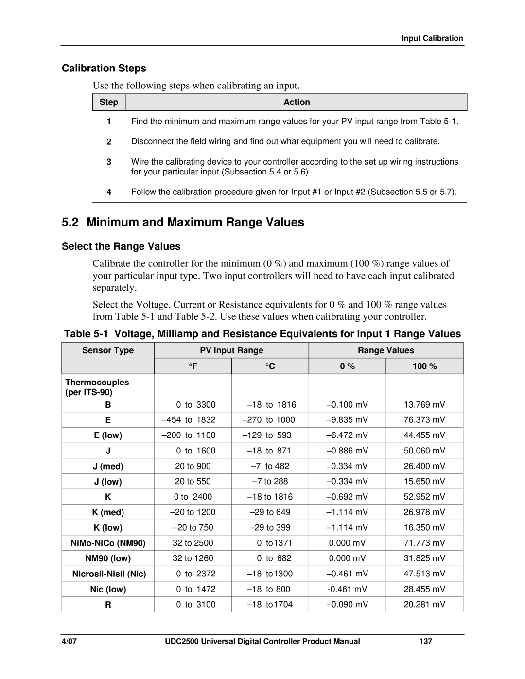
Select the Range Values
Calibrate the controller for the minimum (0 %) and maximum (100 %) range values of your particular input type. Two input controllers will need to have each input calibrated separately.
Select the Voltage, Current or Resistance equivalents for 0 % and 100 % range values from Table
Table
Sensor Type
PV Input Range |
|
| Range Values | ||
°F |
| °C | 0 % |
| 100 % |
|
|
|
|
|
|
Thermocouples |
|
|
|
|
(per |
|
|
|
|
B | 0 | to 3300 | 1816 | |
|
|
|
| |
E | 1000 | |||
|
|
|
| |
E (low) | 593 | |||
|
|
|
|
|
J | 0 | to 1600 | 871 | |
J (med) | 20 to 900 | |||
|
|
| ||
J (low) | 20 to 550 | |||
|
|
| ||
K | 0 to 2400 | |||
|
|
| ||
K (med) | ||||
|
|
| ||
K (low) | ||||
|
|
| ||
32 to 2500 | 0 to1371 | |||
|
|
|
| |
NM90 (low) | 32 to 1260 | 0 to | 682 | |
|
|
|
| |
0 | to 2372 | |||
|
|
|
|
|
Nic (low) | 0 | to 1472 | 800 | |
|
|
|
| |
R | 0 | to 3100 | ||
|
|
|
|
|
13.769 mV
76.373 mV
44.455 mV
50.060 mV
26.400 mV
15.650 mV
52.952 mV
26.978 mV
16.350 mV
71.773 mV
31.825 mV
47.513 mV
28.455 mV
20.281 mV
4/07 | UDC2500 Universal Digital Controller Product Manual | 137 |