Troubleshooting/Service
Procedure #1
Table
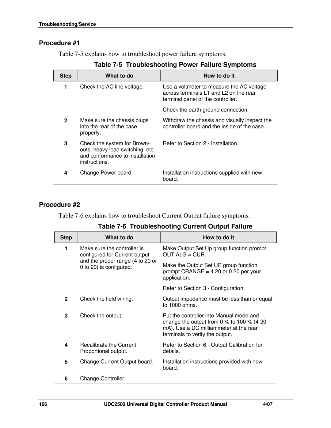
Table 7-5 Troubleshooting Power Failure Symptoms
Step | What to do | How to do it |
1 | Check the AC line voltage. | Use a voltmeter to measure the AC voltage |
|
| across terminals L1 and L2 on the rear |
|
| terminal panel of the controller. |
|
| Check the earth ground connection. |
2 | Make sure the chassis plugs | Withdraw the chassis and visually inspect the |
| into the rear of the case | controller board and the inside of the case. |
| properly. |
|
3 | Check the system for Brown- | Refer to Section 2 - Installation. |
| outs, heavy load switching, etc., |
|
| and conformance to installation |
|
| instructions. |
|
4 | Change Power board. | Installation instructions supplied with new |
|
| board. |
|
|
|
Procedure #2
Table
Table 7-6 Troubleshooting Current Output Failure
Step | What to do | How to do it |
1 | Make sure the controller is | Make Output Set Up group function prompt |
| configured for Current output | OUT ALG = CUR. |
| and the proper range (4 to 20 or | Make the Output Set UP group function |
| 0 to 20) is configured. | |
| prompt CRANGE = | |
|
| |
|
| application. |
|
| Refer to Section 3 - Configuration. |
2 | Check the field wiring. | Output impedance must be less than or equal |
|
| to 1000 ohms. |
3 | Check the output. | Put the controller into Manual mode and |
|
| change the output from 0 % to 100 % |
|
| mA). Use a DC milliammeter at the rear |
|
| terminals to verify the output. |
4 | Recalibrate the Current | Refer to Section 6 - Output Calibration for |
| Proportional output. | details. |
5 | Change Current Output board. | Installation instructions provided with new |
|
| board. |
6Change Controller
166 | UDC2500 Universal Digital Controller Product Manual | 4/07 |
