|
|
|
|
|
|
|
| Configuration |
|
|
|
|
|
|
|
|
| ||
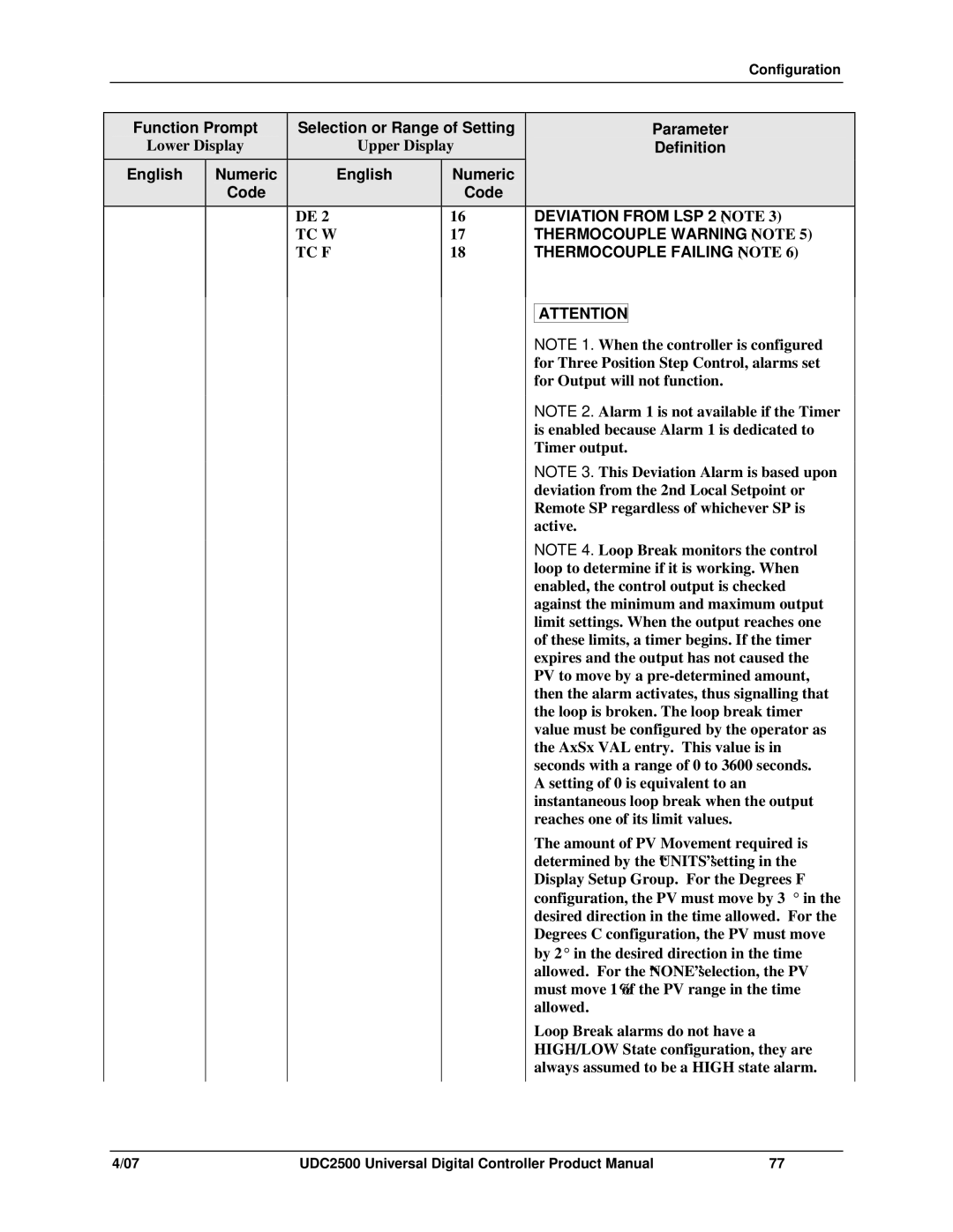
| Function Prompt | Selection or Range of Setting |
|
| Parameter | ||||
| Lower Display |
| Upper Display |
|
| Definition | |||
| English | Numeric |
| English | Numeric |
|
|
|
|
|
| Code |
|
| Code |
|
|
|
|
|
|
| DE 2 |
| 16 |
| DEVIATION FROM LSP 2 (NOTE 3) | ||
|
|
| TC W |
| 17 |
| THERMOCOUPLE WARNING (NOTE 5) | ||
|
|
| TC F |
| 18 |
| THERMOCOUPLE FAILING (NOTE 6) | ||
|
|
|
|
|
|
|
|
| |
|
|
|
|
|
|
|
|
| |
|
|
|
|
|
|
| ATTENTION | ||
|
|
|
|
|
|
| NOTE 1. When the controller is configured | ||
|
|
|
|
|
|
| for Three Position Step Control, alarms set | ||
|
|
|
|
|
|
| for Output will not function. | ||
|
|
|
|
|
|
| NOTE 2. Alarm 1 is not available if the Timer | ||
|
|
|
|
|
|
| is enabled because Alarm 1 is dedicated to | ||
|
|
|
|
|
|
| Timer output. | ||
|
|
|
|
|
|
| NOTE 3. This Deviation Alarm is based upon | ||
|
|
|
|
|
|
| deviation from the 2nd Local Setpoint or | ||
|
|
|
|
|
|
| Remote SP regardless of whichever SP is | ||
|
|
|
|
|
|
| active. | ||
|
|
|
|
|
|
| NOTE 4. Loop Break monitors the control | ||
|
|
|
|
|
|
| loop to determine if it is working. When | ||
|
|
|
|
|
|
| enabled, the control output is checked | ||
|
|
|
|
|
|
| against the minimum and maximum output | ||
|
|
|
|
|
|
| limit settings. When the output reaches one | ||
|
|
|
|
|
|
| of these limits, a timer begins. If the timer | ||
|
|
|
|
|
|
| expires and the output has not caused the | ||
|
|
|
|
|
|
| PV to move by a | ||
|
|
|
|
|
|
| then the alarm activates, thus signalling that | ||
|
|
|
|
|
|
| the loop is broken. The loop break timer | ||
|
|
|
|
|
|
| value must be configured by the operator as | ||
|
|
|
|
|
|
| the AxSx VAL entry. This value is in | ||
|
|
|
|
|
|
| seconds with a range of 0 to 3600 seconds. | ||
|
|
|
|
|
|
| A setting of 0 is equivalent to an | ||
|
|
|
|
|
|
| instantaneous loop break when the output | ||
|
|
|
|
|
|
| reaches one of its limit values. | ||
|
|
|
|
|
|
| The amount of PV Movement required is | ||
|
|
|
|
|
|
| determined by the “UNITS” setting in the | ||
|
|
|
|
|
|
| Display Setup Group. For the Degrees F | ||
|
|
|
|
|
|
| configuration, the PV must move by 3° in the | ||
|
|
|
|
|
|
| desired direction in the time allowed. For the | ||
|
|
|
|
|
|
| Degrees C configuration, the PV must move | ||
|
|
|
|
|
|
| by 2° in the desired direction in the time | ||
|
|
|
|
|
|
| allowed. For the “NONE” selection, the PV | ||
|
|
|
|
|
|
| must move 1% of the PV range in the time | ||
|
|
|
|
|
|
| allowed. | ||
|
|
|
|
|
|
| Loop Break alarms do not have a | ||
|
|
|
|
|
|
| HIGH/LOW State configuration, they are | ||
|
|
|
|
|
|
| always assumed to be a HIGH state alarm. | ||
|
|
|
|
|
|
|
|
|
|
4/07 | UDC2500 Universal Digital Controller Product Manual | 77 |