Configuration
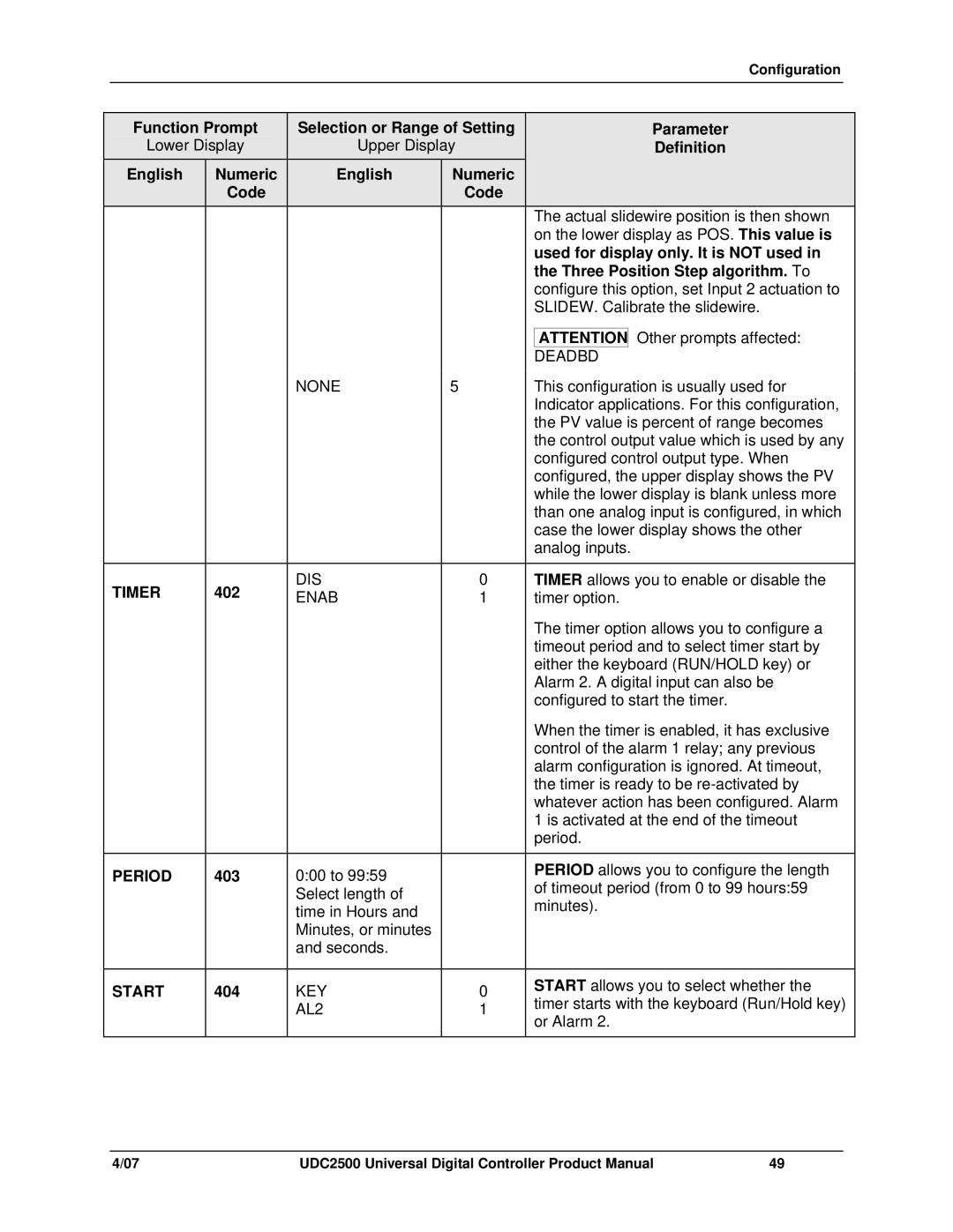
| Function Prompt |
| Selection or Range of Setting |
|
| Parameter | ||||
| Lower Display |
| Upper Display |
|
| Definition | ||||
| English | Numeric |
|
| English | Numeric |
|
|
|
|
|
| Code |
|
|
| Code |
|
|
|
|
|
|
|
|
|
|
|
|
| The actual slidewire position is then shown | |
|
|
|
|
|
|
|
|
| on the lower display as POS. This value is | |
|
|
|
|
|
|
|
|
| used for display only. It is NOT used in | |
|
|
|
|
|
|
|
|
| the Three Position Step algorithm. To | |
|
|
|
|
|
|
|
|
| configure this option, set Input 2 actuation to | |
|
|
|
|
|
|
|
|
| SLIDEW. Calibrate the slidewire. | |
|
|
|
|
|
|
|
|
|
| Other prompts affected: |
|
|
|
|
|
|
|
|
| ATTENTION | |
|
|
|
|
|
|
|
|
| DEADBD |
|
|
|
|
|
| NONE | 5 |
| This configuration is usually used for | ||
|
|
|
|
|
|
|
|
| Indicator applications. For this configuration, | |
|
|
|
|
|
|
|
|
| the PV value is percent of range becomes | |
|
|
|
|
|
|
|
|
| the control output value which is used by any | |
|
|
|
|
|
|
|
|
| configured control output type. When | |
|
|
|
|
|
|
|
|
| configured, the upper display shows the PV | |
|
|
|
|
|
|
|
|
| while the lower display is blank unless more | |
|
|
|
|
|
|
|
|
| than one analog input is configured, in which | |
|
|
|
|
|
|
|
|
| case the lower display shows the other | |
|
|
|
|
|
|
|
|
| analog inputs. | |
|
|
|
|
|
|
|
|
|
| |
| TIMER | 402 |
|
| DIS | 0 |
|
| TIMER allows you to enable or disable the | |
|
|
| ENAB | 1 |
|
| timer option. | |||
|
|
|
|
|
|
|
|
| The timer option allows you to configure a | |
|
|
|
|
|
|
|
|
| timeout period and to select timer start by | |
|
|
|
|
|
|
|
|
| either the keyboard (RUN/HOLD key) or | |
|
|
|
|
|
|
|
|
| Alarm 2. A digital input can also be | |
|
|
|
|
|
|
|
|
| configured to start the timer. | |
|
|
|
|
|
|
|
|
| When the timer is enabled, it has exclusive | |
|
|
|
|
|
|
|
|
| control of the alarm 1 relay; any previous | |
|
|
|
|
|
|
|
|
| alarm configuration is ignored. At timeout, | |
|
|
|
|
|
|
|
|
| the timer is ready to be | |
|
|
|
|
|
|
|
|
| whatever action has been configured. Alarm | |
|
|
|
|
|
|
|
|
| 1 is activated at the end of the timeout | |
|
|
|
|
|
|
|
|
| period. | |
|
|
|
|
|
|
|
|
|
| |
| PERIOD | 403 |
|
| 0:00 to 99:59 |
|
|
| PERIOD allows you to configure the length | |
|
|
|
|
|
| of timeout period (from 0 to 99 hours:59 | ||||
|
|
|
|
| Select length of |
|
|
| ||
|
|
|
|
|
|
|
| minutes). | ||
|
|
|
|
| time in Hours and |
|
|
| ||
|
|
|
|
| Minutes, or minutes |
|
|
|
|
|
|
|
|
|
| and seconds. |
|
|
|
|
|
|
|
|
|
|
|
|
|
|
| |
| START | 404 |
|
| KEY | 0 |
|
| START allows you to select whether the | |
|
|
|
|
| timer starts with the keyboard (Run/Hold key) | |||||
|
|
|
|
| AL2 | 1 |
|
| ||
|
|
|
|
|
|
| or Alarm 2. | |||
|
|
|
|
|
|
|
|
| ||
|
|
|
|
|
|
|
|
|
|
|
4/07 | UDC2500 Universal Digital Controller Product Manual | 49 |