INSTALLATIONS
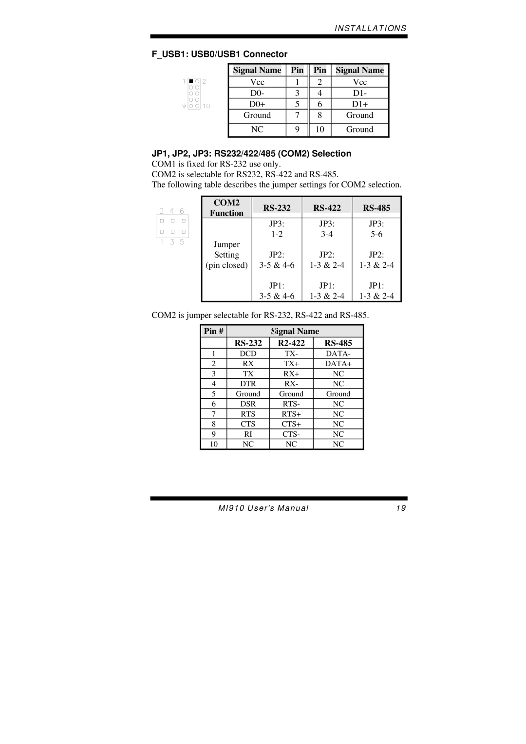
F_USB1: USB0/USB1 Connector
| Signal Name |
|
| Pin |
|
| Pin |
|
| Signal Name |
|
| Vcc |
| 1 |
| 2 |
|
| Vcc |
| ||
| D0- |
| 3 |
| 4 |
|
| D1- |
| ||
| D0+ |
| 5 |
| 6 |
|
| D1+ |
| ||
| Ground |
| 7 |
| 8 |
|
| Ground |
| ||
|
|
|
|
|
|
|
|
|
| ||
| NC |
| 9 |
| 10 |
|
| Ground |
| ||
|
|
|
|
|
|
|
|
|
|
|
|
JP1, JP2, JP3: RS232/422/485 (COM2) Selection COM1 is fixed for
COM2 is selectable for RS232,
The following table describes the jumper settings for COM2 selection.
COM2 |
|
|
|
|
|
|
Function |
|
|
| |||
|
|
|
|
|
| |
|
| JP3: |
| JP3: |
| JP3: |
Jumper |
|
|
| |||
|
|
|
|
|
| |
Setting |
| JP2: |
| JP2: |
| JP2: |
(pin closed) |
|
|
| |||
|
| JP1: |
| JP1: |
| JP1: |
|
|
|
|
COM2 is jumper selectable for
Pin # |
|
| Signal Name |
| |
|
|
| |||
1 |
| DCD | TX- |
| DATA- |
2 |
| RX | TX+ |
| DATA+ |
3 |
| TX | RX+ |
| NC |
4 |
| DTR | RX- |
| NC |
5 |
| Ground | Ground |
| Ground |
6 |
| DSR | RTS- |
| NC |
7 |
| RTS | RTS+ |
| NC |
8 |
| CTS | CTS+ |
| NC |
9 |
| RI | CTS- |
| NC |
10 |
| NC | NC |
| NC |
MI910 User’s Manual | 19 |