Manuals
/
Intel
/
Computer Equipment
/
Computer Hardware
Intel
MI910F
user manual
Board Dimensions
Models:
MI910
MI910F
1
8
66
66
Download
66 pages
35.67 Kb
5
6
7
8
9
10
11
12
Page 8
Image 8
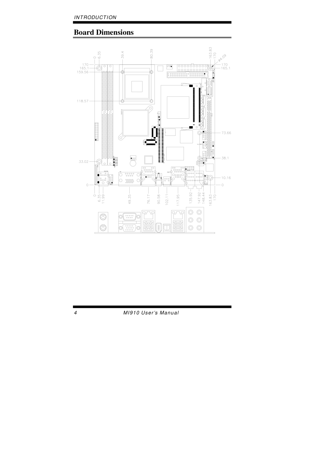
INTRODUCTION
[
Board Dimensions
4
MI910 User’s Manual
Page 7
Page 9
Page 8
Image 8
Page 7
Page 9
Contents
Intel CoreTM 2 Duo Celeron GM965
Version
Acknowledgments
Table of Contents
MI910 Mini ITX Motherboard
Introduction
Product Description
Checklist
MI910 Specifications
CPU FSB
Board Dimensions
Installations
Installing the CPU
Installing the Memory
Lock
Setting the Jumpers
Jumper Locations on MI910
JP5 LCD Panel Power Selection
JBAT1 Clear Cmos Setting
JP9 PCI/PCIE Riser Card Selection
JP8 CompactFlash Slave/Master Selection
Connectors on MI910
Connector Locations on MI910
MI910 Solder Side
CN1 PS/2 Keyboard and PS/2 Mouse Connectors
CN2, CN3 COM1 and VGA Connector
FAN2 CPU Fan Power Connector
IDE1 IDE Connector
FDD1 Floppy Drive Connector
ATX1 ATX Power Supply Connector
J1 Fpanel System Function Connector
Power LED Pins 11 Pin # Signal Name
FUSB1 USB0/USB1 Connector
COM2
J3, J4 Lvds Connectors 1st channel, 2nd channel
J5 LCD Backlight Connector
J7 Mini PCI Connector CN8, CN9 Sata Connectors
J2 COM2 Serial Port
J10 SPI Flash Connector factory use only
J11 1394 Connector
J12 Front Audio Connector
J8 Digital I/O
J14 IrDA Connector
SDVOCCLK+ Sdvocclk
Headers and Connectors on MI910 Daughter Cards
JP4
RED
ID391 J2 DVI Connector
This page is intentionally left blank
Bios Setup
Bios Introduction
Bios Setup
Phoenix AwardBIOS Cmos Setup Utility
Standard Cmos Setup
Date
Drive a / Drive B
Time
IDE Channel Master/Slave
Video
Halt On
Advanced Bios Features
CPU Feature
Hard Disk Boot Priority
Virus Warning
Quick Power On Self Test
First/Second/Third Boot Device
Boot Other Device
Boot Up Floppy Seek
Typematic Delay Msec
Apic Mode
Security Option
MPS Version Control for OS
Memory Hole At 15M-16M
Advanced Chipset Features
System Bios Cacheable
Panel Number
On-Chip VGA Setting
Panel Scaling
Integrated Peripherals
OnChip IDE Device
IDE HDD Block Mode
On-chip Primary PCI IDE Enabled
On-chip Primary/Secondary PCI IDE
IDE Primary/Secondary Master/Slave PIO
On-Chip Serial ATA Setting
Power on Function
KB Power on Password
Hot Key Power on
Uart Mode Select
Onboard Serial Port
Pwron After PWR-Fail
USB 1.0 Controller
Power Management Setup
RUN Vgabios if S3 Resume
Power Management
Acpi Function
Suspend Mode
HDD Power Down
Power On by Ring
Video Off Method
Resume by Alarm
Reload Global Timer Events
PNP/PCI Configurations
CPU Warning Temperature
Temperatures/Voltages
Shutdown Temperature
1st 2st Smart Fan Temperature
Spread Spectrum Modulated
Frequency/Voltage Control
Auto Detect PCI Clk
Load Fail-Safe Defaults
Load Optimized Defaults
Set Supervisor Password
Save & Exit Setup
Drivers Installation
Intel Chipset Software Installation Utility
Click IntelR Chipset Software Installation Utility
Drivers Installation
VGA Drivers Installation
Click IntelR GM965Chipset Family Graphics Driver
Important Note
AC97 Codec Audio Driver Installation
Click Realtek AC97 Codec Audio Driver
LAN Drivers Installation
Click Install Base Software to continue
Driver Installation
Appendix
O Port Address Map
Interrupt Request Lines IRQ
Level Function
Watchdog Timer Configuration
Sample Code
Appendix
OutportbW627EHFINDEXPORT, W627EHFLOCK
W627EHFLOCK
Top
Page
Image
Contents