BIOS SETUP
Advanced Chipset Features
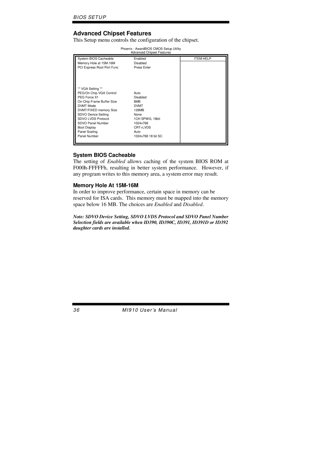
This Setup menu controls the configuration of the chipset.
Phoenix - AwardBIOS CMOS Setup Utility
Advanced Chipset Features
|
|
|
|
|
| System BIOS Cacheable | Enabled | ITEM HELP |
|
| Memory Hole at | Disabled |
|
|
| PCI Express Root Port Func | Press Enter |
|
|
| ** VGA Setting ** |
|
|
|
| PEG/On Chip VGA Control | Auto |
|
|
| PEG Force X1 | Disabled |
|
|
| 8MB |
|
| |
| DVMT Mode | DVMT |
|
|
| DVMT/FIXED memory Size | 128MB |
|
|
| SDVO Device Setting | None |
|
|
| SDVO LVDS Protocol | 1CH SPWG, 18bit |
|
|
| SDVO Panel Number | 1024x768 |
|
|
| Boot Display | CRT+LVDS |
|
|
| Panel Scaling | Auto |
|
|
| Panel Number | 1024x768 18 bit SC |
|
|
|
|
|
|
|
|
|
|
|
|
System BIOS Cacheable
The setting of Enabled allows caching of the system BIOS ROM at
Memory Hole At 15M-16M
In order to improve performance, certain space in memory can be reserved for ISA cards. This memory must be mapped into the memory space below 16 MB. The choices are Enabled and Disabled.
Note: SDVO Device Setting, SDVO LVDS Protocol and SDVO Panel Number Selection fields are available when ID390, ID390C, ID391, ID391D or ID392 daughter cards are installed.
36 | MI910 User’s Manual |