APPENDIX
Appendix
A. I/O Port Address Map
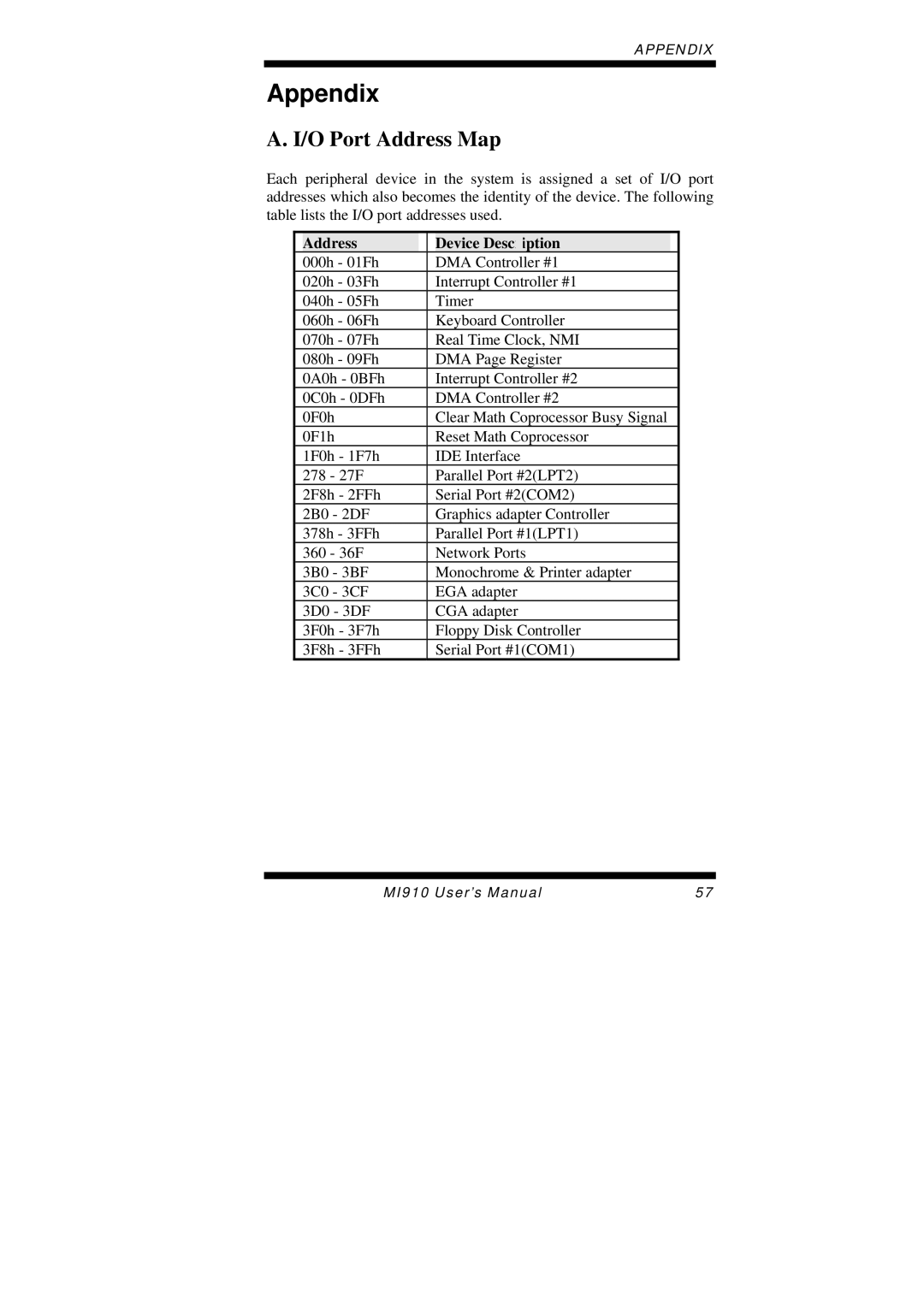
Each peripheral device in the system is assigned a set of I/O port addresses which also becomes the identity of the device. The following table lists the I/O port addresses used.
| Address |
|
| Device Description |
|
| 000h - 01Fh |
|
| DMA Controller #1 |
|
| 020h - 03Fh |
|
| Interrupt Controller #1 |
|
| 040h - 05Fh |
| Timer |
| |
| 060h - 06Fh |
| Keyboard Controller |
| |
| 070h - 07Fh |
| Real Time Clock, NMI |
| |
| 080h - 09Fh |
| DMA Page Register |
| |
| 0A0h - 0BFh |
|
| Interrupt Controller #2 |
|
| 0C0h - 0DFh |
|
| DMA Controller #2 |
|
| 0F0h |
| Clear Math Coprocessor Busy Signal |
| |
| 0F1h |
| Reset Math Coprocessor |
| |
| 1F0h - 1F7h |
| IDE Interface |
| |
| 278 - 27F |
| Parallel Port #2(LPT2) |
| |
| 2F8h - 2FFh |
| Serial Port #2(COM2) |
| |
| 2B0 - 2DF |
| Graphics adapter Controller |
| |
| 378h - 3FFh |
| Parallel Port #1(LPT1) |
| |
| 360 - 36F |
| Network Ports |
| |
| 3B0 - 3BF |
| Monochrome & Printer adapter |
| |
| 3C0 - 3CF |
| EGA adapter |
| |
| 3D0 - 3DF |
| CGA adapter |
| |
| 3F0h - 3F7h |
|
| Floppy Disk Controller |
|
| 3F8h - 3FFh |
| Serial Port #1(COM1) |
| |
MI910 User’s Manual | 57 |
