Manuals
/
Intel
/
Computer Equipment
/
Network Card
Intel
MIC-3321, 3U Compact PCI
user manual
Serial ATA0 7pin connector
Models:
3U Compact PCI
MIC-3321
1
50
50
Download
50 pages
38.27 Kb
43
44
45
46
47
48
49
50
Specifications
Install
Function Block Diagram
Password
Load Optimized Defaults
Typematic Delay Msec
Connecting Peripherals
Warranty
Dimension
Hardware Configuration
Page 50
Image 50
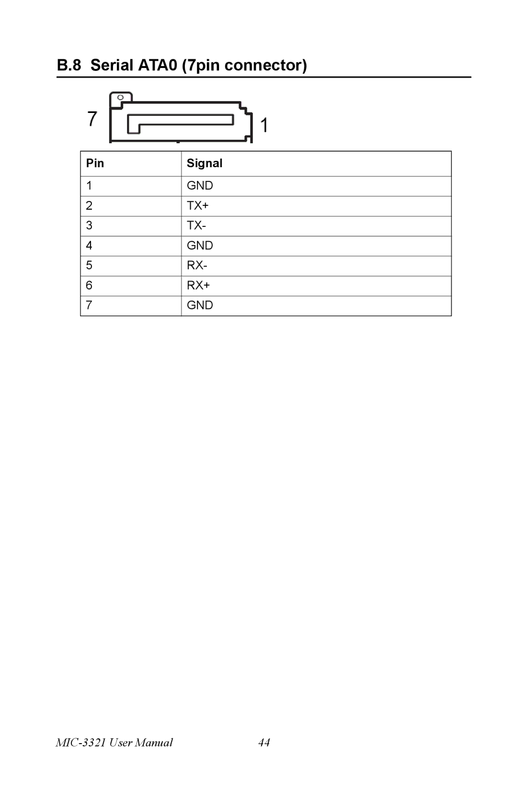
B.8 Serial ATA0 (7pin connector)
Pin
1
2
3
4
5
6
7
Signal
GND
TX+
TX-
GND
RX-
RX+
GND
MIC-3321
User Manual
44
Page 49
Page 50
Page 50
Image 50
Page 49
Page 50
Contents
MIC-3321
Copyright Notice
Acknowledgements
Product Warranty
CE Notification
Packing List
Safety Precaution Static Electricity
Technical Support and Assistance
Contents
CompactFlash Interface
Hardware Configuration
Ordering Information
Introduction
Compact Mechanical Design
Standard SBC Functions
Specifications
Battery-backup RAM 512 KB
System Memory
Storage Temperature -40 ~ 80 C Board Weight 0.6 kg
Function Block Diagram
Mechanical and Environmental Specifications
Display
Board Dimensions
Dip Switch Settings
Switch Locations
MIC-3321 Switch Descriptions
Safety Precautions
MIC-3321 S2 Location 2F
Page
Connecting Peripherals
Connectors
MIC-3321 Connector Locations 1F
MIC-3521 Connectors
MIC-3321 Connectors Overview
Card Installation
To install a card
Chassis Installation/Removal
To remove a card
Software Configuration
Utilities and Drivers
Intel Chipset Software Installation Utility
Overview
Intel VGA Graphics Driver
Award Bios Setup
Entering Setup
Setup Program Initial Screen
Date
Standard Cmos Setup
IDE Device Setup
Time
Memory
Advanced Bios Features Setup
Halt On
Virus Warning
Hard Disk Boot Priority
CPU Thermal Monitor
Boot Up NumLock Status
Quick Power On Self Test
First/Second/Third Boot Device and Boot Other Device
CPU L1 & L2 Cache
Setupdefault
Typematic Rate Setting
Typematic Delay Msec
Typematic Rate Chars/Sec
CAS Latency Time
Advanced Chipset Features Setup
Dram Timing Configuration
System Bios Cache-able
Dram RAS# to CAS# Delay
Precharge delay tRAS
Video Bios Cacheable
Integrated Peripherals
IDE Primary/Secondary Master/Slave PIO
IDE HDD Block Mode
On-Chip Primary Sata / Secondary Pata PCI IDE
IDE Primary/Secondary Master/Slave Udma
USB Keyboard Support
USB Controller
USB 2.0 Controller
USB Mouse Support
Init Display Fiest
5 PNP/PCI Configuration Setup
Reset Configuration Data
IRQ Resources
PC Health Status
Resource Controlled By
PCI/VGA Palette Snoop
PC Health Status setup screen
CPU Warning Temperature
Spread Spectrum
Load Optimized Defaults
Spread Spectrum Control
Set Password
Save & Exit Setup
Exit Without Saving
Programming Watchdog Timer
Appendix a Watchdog Timer Programming
Data Time Interval 01 0.25 sec
Pin Assignment
Appendix B Pin Assignment
CompactFlash Interface
Table B.2 CompactFlash Interface Pin Definitions
VGA Connector
USB 2.0 Ports
PS/2 Keyboard and Mouse Connector
COM port
Ethernet 10/100/1000Base-T RJ-45 Connector
Secondary IDE 44-pin 2mm Conn
Table B.7 Secondary IDE Connectors 2.5 HDD
Serial ATA0 7pin connector
Top
Page
Image
Contents