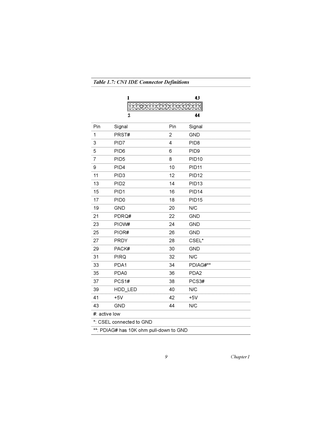
MIC-3358 specifications
The Intel MIC-3358, also known as the Intel Many Integrated Core (MIC) architecture, represents a pivotal innovation in high-performance computing and parallel processing. This product is part of Intel's Xeon Phi family and was specifically designed to tackle demanding workloads, making it a popular choice for research institutions and industries requiring significant computational power.One of the standout features of the MIC-3358 is its many-core architecture, which integrates numerous processor cores on a single chip. This allows for massively parallel processing capabilities, enabling the execution of multiple tasks simultaneously. With a total of 60 cores, the MIC-3358 can deliver exceptional performance for applications such as scientific simulations, data analytics, and machine learning.
The architecture of the MIC-3358 is notable for its x86 compatibility. Unlike traditional GPUs, the MIC-3358 can run standard x86 applications unmodified, ensuring seamless integration into existing workflows and simplifying development. This feature helps users leverage their existing software tools and libraries without requiring extensive porting or adaptation.
Another key technology is the incorporation of advanced memory architecture, featuring a high-bandwidth memory system. The MIC-3358 supports GDDR5 memory, enabling rapid data transfer rates that are crucial for performance-intensive applications. This, combined with an efficient memory architecture, helps overcome memory bandwidth limitations often encountered in high-performance computing.
The MIC-3358 also includes support for Intel's advanced vector extensions (AVX) and AVX-512, which enhance the processing of vector operations and allow for more efficient data handling. This makes the MIC-3358 particularly effective for workloads that involve large datasets and require complex mathematical computations.
Energy efficiency is another defining characteristic of the MIC-3358. Despite its high core count, the architecture is designed to deliver optimal performance per watt, making it suitable for large data centers where power consumption is a crucial factor.
In summary, the Intel MIC-3358 stands out due to its many-core architecture, x86 compatibility, high-bandwidth memory support, advanced vector instructions, and energy efficiency. These features collectively position it as a powerful solution for high-performance computing challenges, enabling a wide array of applications across various sectors. As the demand for computational resources continues to grow, the MIC-3358 remains a vital component in the landscape of advanced computing technologies.

