PCM-6896
Copyright Notice
Acknowledgments
Packing List
FCC STATEMENT
A Message to the Customer
AAEON Customer Services
Technical Support
Product Warranty
Dear Customer
Chapter Two Hardware Installation
Chapter One General Information
Contents
Chapter3AwardBIOSetup
Chapter 4 Driver Installation
Win NT LAN
Win 2000 VGA
Win 2000 Audio
General Information
Sections include Card specifications Card layout and dimensions
This chapter gives background informa- tion on the PCM-6896
RE1 TP AH C
Introduction
Features
Supports both Intel FC-PGA Pentium III and Celeron CPU’s
High Speed Micro AGP 2X for VGA function onboard
One 10/100 Base-T Fast Ethernet Supports H/W status monitoring
Specifications
IrDA port Support SIR and CIR Connector One 6-pin 2.54mm pin header
USB connectors Two 10-pin header onboard supports four USB ports
Connector Two 10-pin 2.00mm pin header
Connector 8-pin 2.54mm pin header
Expansion Interface PC/104 and PC/104 Plus Connector
Audio Interface Chipset 815E
Flat Panel/CRT Interface
Ethernet Interface
Power Supply voltage +5V, +12V, +3.3V, -5V, -12V
Operating temperature 32 to 140 degrees F 0-60 degrees C
Board Size 8” L x 5.75” W 203mm x 146mm Weight 1.2 lb. 0.5Kg
SDD Interface
Board Layout
Board Dimensions
Installation
C H A P T E R
Safety precautions
Removing the CPU
Removing a CPU
Installing A CPU
Setting jumpers
OpenClosedClosed
Open
Closed
Installing DRAM DIMMs
Memory Installation Procedures
System Memory
Supplementary information about DIMM
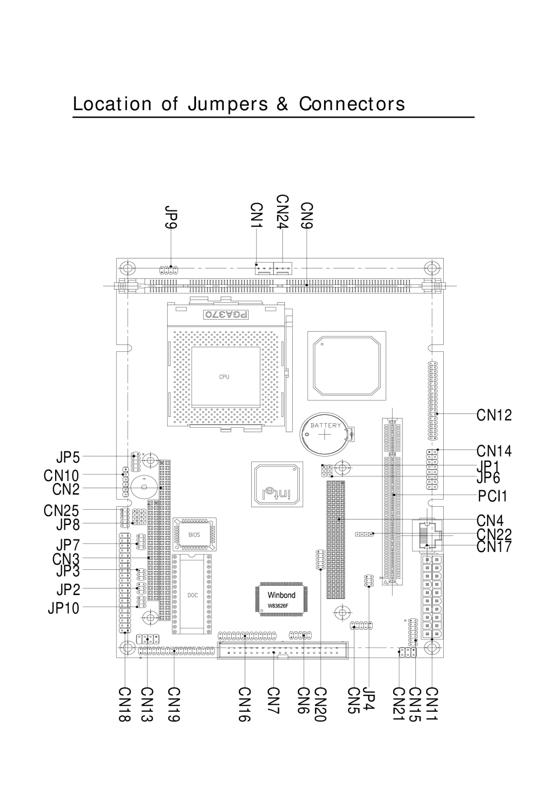
Location of Jumpers & Connectors
CN12 CN14 JP1 JP6 PCI1 CN4 CN22 CN17
JP5 CN10 CN2 CN25 JP8 JP7 CN3 JP3
JP10
List of Jumpers
Jumpers
List of Connectors
Connectors
Clear CMOS Selection JP1
JP2 & JP3 For COM3 & COM4 Selec- tion
1 3 2 4
RI default
1 3 2 4
Front Panel Connectors JP5
Speaker Out and Line out JP4
PC/104 Plus Voltage Select JP6
Signal
RS-232/422/485 COM 2 JP8, JP7
3 6 9 1 4 7
CPU/SDRAM Speed Select JP9
Auto Detect
Auto Detect
CPU/66MHzSDRAM100MHz
DiskOnChip socket
DiskOnChip DOC 2000 Installation
Configure DOC as a boot device
DiskOnChip Address Selection JP10
CPU Fan Power Connector CN1
Fan Power Connector CN24
CPU and System Fan Power Connector CN1 & CN24
Signal
USB Connector CN5 & CN6
USB Connector CN5
USB Connector CN6
IDE Hard Drive Connectors CN7
Primary IDE Hard Drive Connector CN7
Connecting the hard drive
IDE Hard Drive Connector CN7
IR Connector CN10
ATX Power Connector CN11
IrDA connector CN10 pin definitions
ATX Power Connector CN11
Digital Visual Interface Connector CN12
Keyboard and Mouse Connector CN13
Pin Signal
VGA Display Connector CN14
VGA Display Conncetor CN14
Audio Connector CN15
Parallel Port Connector CN16
Audio Connector CN
100 Base-Tx Ethernet Connector CN17
RJ-45 Ethernet Connector CN17
Floppy drive connector CN19
Connecting the floppy drive
Please refer to the pin definitions on the next page
Floppy Drive Connector CN19
Signal
Signal
Digital I/O Connector CN20
Audio Out Connector 1 Watt CN22
CN25 Wake On Lan Pins
CN25 AT/ATX Power Select Pins
Audio Out Connector 1 Watt CN22
Compact Flash Connector
Award BIOS Setup
C H A P T E R
Starting setup
Getting help
In Case of Problems
Setup keys
These keys helps you navigate in Setup
Main Setup Menu
Standard CMOS Features
Advanced BIOS Features
Advanced Chipset Features
PnP/PCI Configuration
Load Fail-Safe Defaults
Load Optimized Defaults
Set Supervisor/User Password
Standard CMOS Features
Date and Time Configuration
HARD DISKS
NOTE We recommend that you select type AUTO for all drives
3.Use the IDE HDD AUTO DECTECTION function in Setup
Here is a brief explanation of drive specifications
Sector Number of sectors Mode Auto, Normal, Large, or LBA
Auto The BIOS automatically determines the optimal mode
Drive A Drive B
Halt On
Memory
Base Memory
Extended Memory
Other Memory
Advanced BIOS Features
Virus Warning
Quick Power On Self Test
First/Second/Third/Fourth Boot Device
Boot Up from LAN
CPU Internal Cache/External Cache
Boot Up Floppy Seek
Boot Up NumLock Status
Boot Up System Speed
Swap Floppy Drive
Typematic Rate Setting- Key strokes repeat at a
Typematic Dealy Msec- Sets the delay time
Typematic Rate Chars/Sec- Sets the number
Security Option
HDD S.M.A.R.T Capability
Report No FDD For WIN 95- Wheather report
Enable, Disable
SDRAM RAS-to-CAS Delay
SDRAM CAS Latency Time
SDRAM Cycle Time Tras/Trc
Advanced Chipset Features
System BIOS Cacheable
Video BIOS Cacheable
CPU Latency Timer
Delayed Transaction
Paging Mode Control
AGP Graphics Aperture Size
Display Cache Frequency
System Memory Frequency
RAS-to-CAS Override
Ras# Timing
Ras# Precharge Timing
choices Fast, Slow
Integrated Peripherals
On-Chip Primary PCI IDE
On-Chip Secondary PCI IDE
IDE Primary/Secondary Master/Slave PIO
IDE HDD Block Mode
Power on Function
KB Power on Password
USB Controller
Hot Key Power On
UART Mode Select
UART2 Duplex Mode
Onboard FDC Controller
Parallel Port Mode
ECP Mode Use DMA
Onboard Serial Ports 1, 2,3,4
Onboard Parallel Port
Watch Dog Timer
sec, 20 sec, 40 sec, 1 min, 2 min, 4 min
Power Management Setup
Power Management
ACPI Function
Video Off Method
Initial display power management signaling
This determines the manner in which the monitor is blanked
V/H SYNC + Blank
Suspend Mode
HDD Power Down
Video Off In Suspend
Suspend Type
Power On By Ring
Resume By Alarm
Reload Global Timer Events
Primary IDE Primary IDE Secondary IDE Secondary IDE
PnP/PCI Configurations
PnP OS Installed
Reset Configuration Data
Resources Controlled By
Shutdown Temperature
PC Health Status
Clock By Slight Adjust
Frequency/Voltage Control
Auto Detect DIMM/PCI CLK
Spread Spectrum
Load Fail-Safe Defaults
Load Optimized Default
Set Supervisor Password
ENTER PASSWORD
CONFIRM PASSWORD
Set User Password
ENTER PASSWORD
CONFIRM PASSWORD
Save to CMOS and EXIT
Quit without Saving
Exit Without Saving
DRIVERS INSTALLATION
C H A P T E R
Installing Drivers
Notice Attention
Notice Attention
Installing Chipset Driver for Windows 95/98
The chipset driver must be installed in order to
proceed to LAN, VGA and AUDIO drivers
Installing Ultra ATA Storage Driver for Windows 95/98
Installing LAN for Windows 95/98
==Select the Optional Search for best Lan driver
Installing VGA for Windows 95/98
Installing Audio for Windows 95/98
Installing Security Driver for Windows NT
Please perform this procedure first
Installing Ultra ATA Storage Driver for Windows NT
Installing VGA for Windows NT
Installing Audio for Windows NT
Installing LAN for Windows NT
==Click on Select from list
==Intel Pro Adapter will appear ==Click on OK
Installing VGA for Windows
Installing Audio for Windows
Installing LAN for Windows