Chapter 2 Hardware Configuration
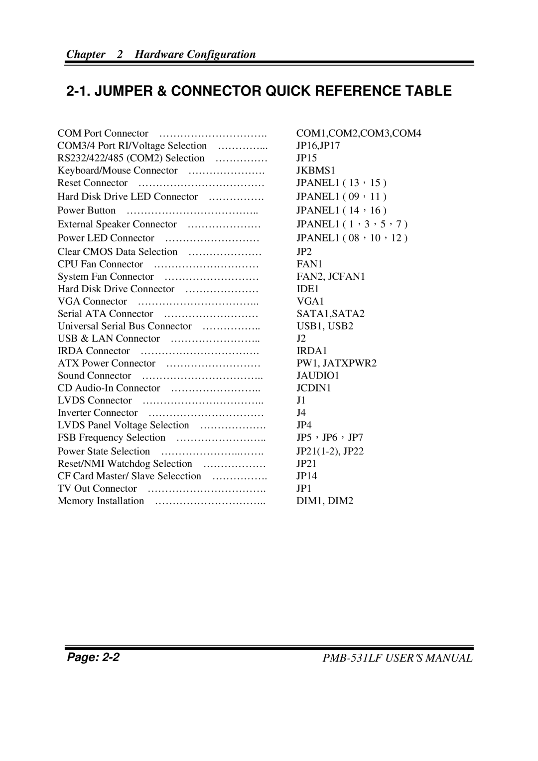
2-1. JUMPER & CONNECTOR QUICK REFERENCE TABLE
COM Port Connector …………………………. | COM1,COM2,COM3,COM4 | |||
COM3/4 Port RI/Voltage Selection | …………... | JP16,JP17 | ||
RS232/422/485 (COM2) Selection | …………… | JP15 | ||
Keyboard/Mouse Connector …………………. | JKBMS1 | |||
Reset Connector | ……………………………… | JPANEL1 ( 13,15 ) | ||
Hard Disk Drive LED Connector |
| ……………. | JPANEL1 ( 09,11 ) | |
Power Button ……………………………….. | JPANEL1 ( 14,16 ) | |||
External Speaker Connector ………………… | JPANEL1 ( 1,3,5,7 ) | |||
Power LED Connector ……………………… | JPANEL1 ( 08,10,12 ) | |||
Clear CMOS Data Selection ………………… | JP2 | |||
CPU Fan Connector ………………………… | FAN1 | |||
System Fan Connector ……………………… | FAN2, JCFAN1 | |||
Hard Disk Drive Connector ………………… | IDE1 | |||
VGA Connector | …………………………….. | VGA1 | ||
Serial ATA Connector ……………………… | SATA1,SATA2 | |||
Universal Serial Bus Connector | …………….. | USB1, USB2 | ||
USB & LAN Connector …………………….. | J2 | |||
IRDA Connector | ……………………………. | IRDA1 | ||
ATX Power Connector ……………………… | PW1, JATXPWR2 | |||
Sound Connector | …………………………….. | JAUDIO1 | ||
CD | JCDIN1 | |||
LVDS Connector | …………………………….. | J1 | ||
Inverter Connector | …………………………… | J4 | ||
LVDS Panel Voltage Selection ………………. | JP4 | |||
FSB Frequency Selection …………………….. | JP5,JP6,JP7 | |||
Power State Selection …………………..……. | ||||
Reset/NMI Watchdog Selection | ……………… | JP21 | ||
CF Card Master/ Slave Selecction |
| ……………. | JP14 | |
TV Out Connector | ……………………………. | JP1 | ||
Memory Installation ………………………….. | DIM1, DIM2 | |||
Page: |