Chapter 2 Hardware Configuration
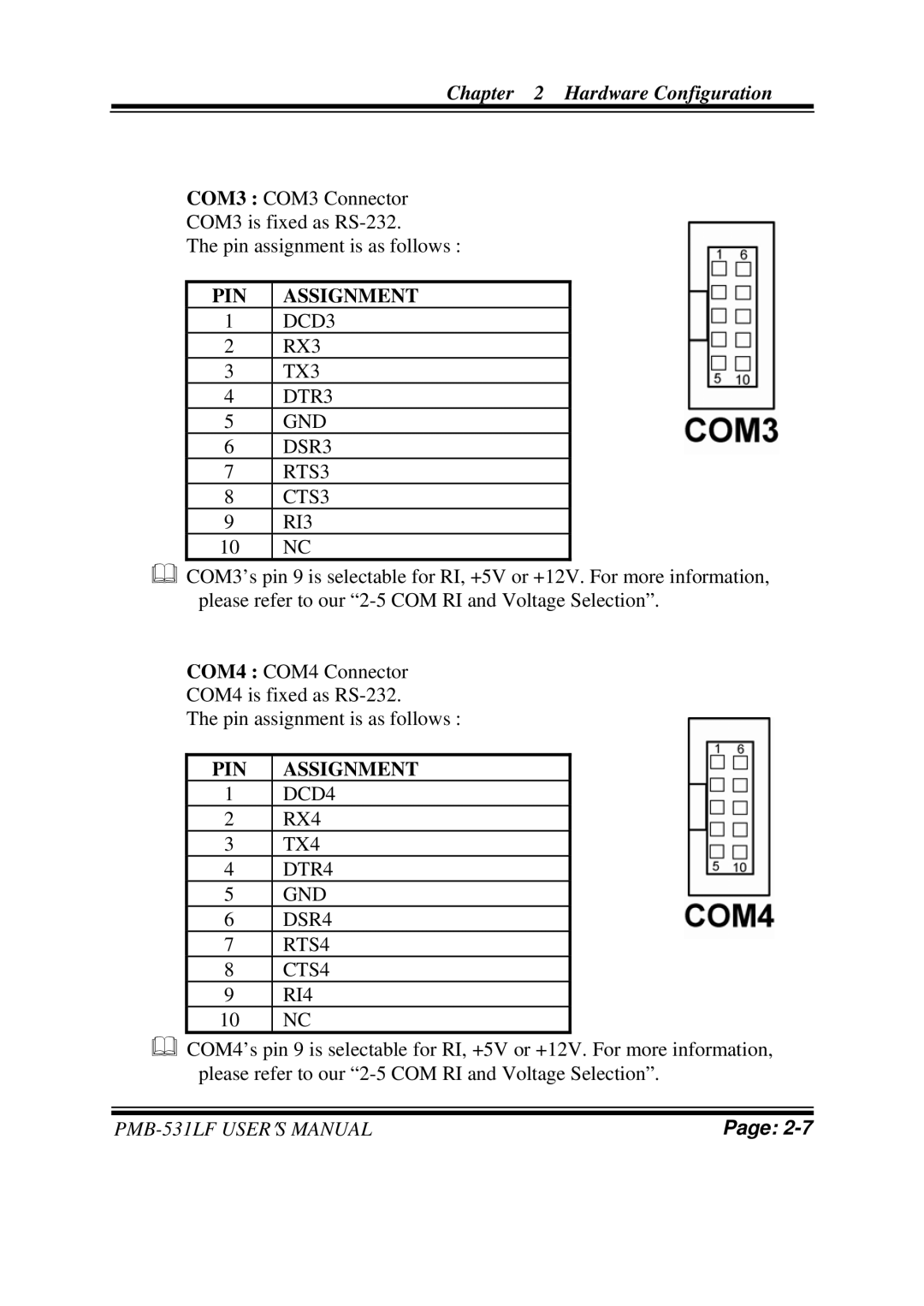
COM3 : COM3 Connector
COM3 is fixed as
The pin assignment is as follows :
PIN | ASSIGNMENT |
1 | DCD3 |
2 | RX3 |
3 | TX3 |
4 | DTR3 |
5 | GND |
6 | DSR3 |
7 | RTS3 |
8 | CTS3 |
9 | RI3 |
10 | NC |
COM3’s pin 9 is selectable for RI, +5V or +12V. For more information, please refer to our
COM4 : COM4 Connector
COM4 is fixed as
The pin assignment is as follows :
PIN | ASSIGNMENT |
1 | DCD4 |
2 | RX4 |
3 | TX4 |
4 | DTR4 |
5 | GND |
6 | DSR4 |
7 | RTS4 |
8 | CTS4 |
9 | RI4 |
10 | NC |
COM4’s pin 9 is selectable for RI, +5V or +12V. For more information, please refer to our
Page: |