Chapter 2 Hardware Configuration
2-20. USB&LAN CONNECTOR
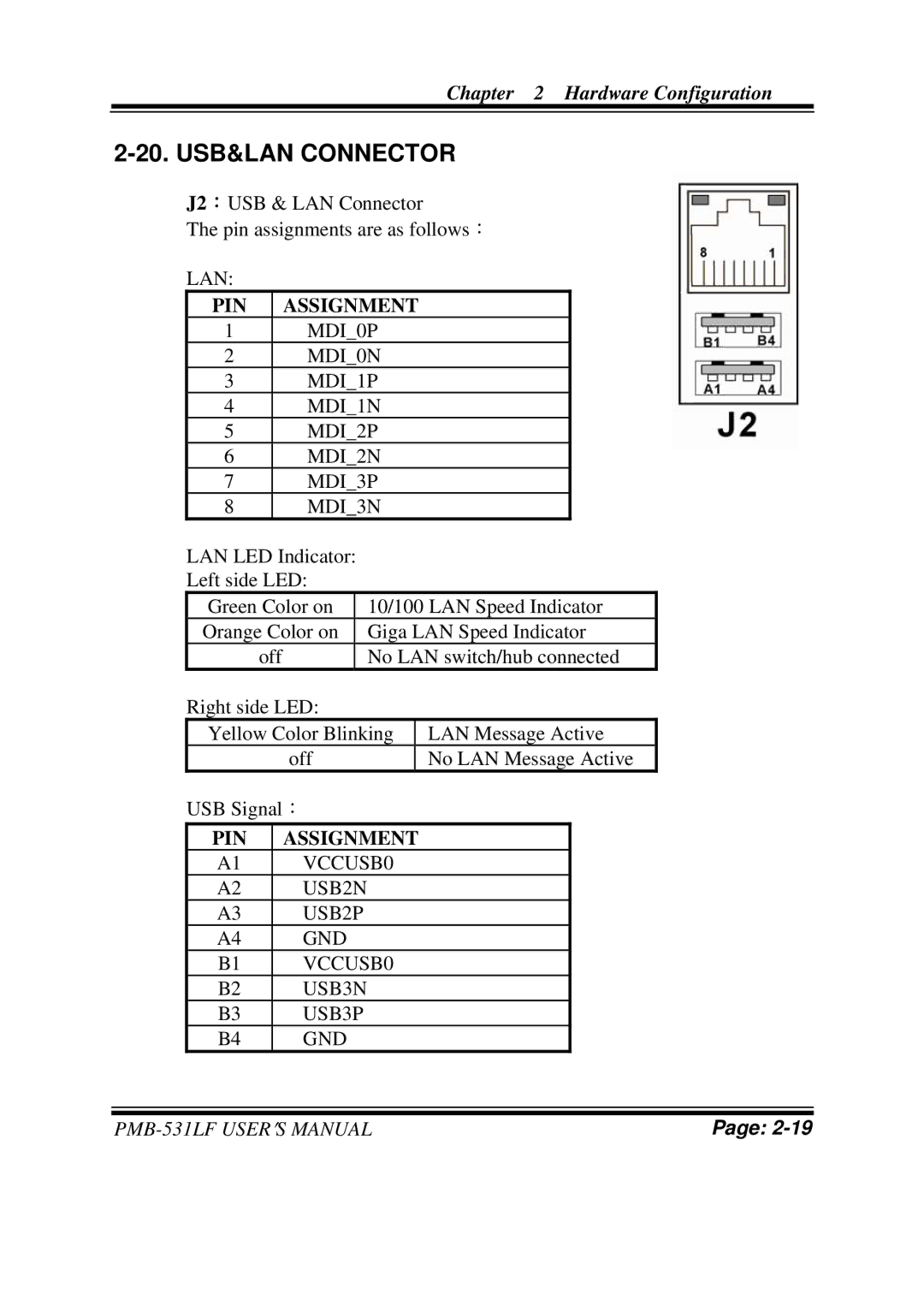
J2:USB & LAN Connector
The pin assignments are as follows:
LAN:
PIN | ASSIGNMENT |
1 | MDI_0P |
2 | MDI_0N |
3 | MDI_1P |
4 | MDI_1N |
5 | MDI_2P |
6 | MDI_2N |
7 | MDI_3P |
8 | MDI_3N |
LAN LED Indicator:
Left side LED:
Green Color on | 10/100 LAN Speed Indicator |
Orange Color on | Giga LAN Speed Indicator |
off | No LAN switch/hub connected |
Right side LED:
| Yellow Color Blinking |
| LAN Message Active |
| ||
|
| off |
| No LAN Message Active |
| |
| USB Signal: |
|
|
| ||
| PIN | ASSIGNMENT |
|
|
| |
| A1 | VCCUSB0 |
|
|
| |
| A2 | USB2N |
|
|
| |
| A3 | USB2P |
|
|
| |
| A4 | GND |
|
|
| |
| B1 | VCCUSB0 |
|
|
| |
| B2 | USB3N |
|
|
| |
| B3 | USB3P |
|
|
| |
| B4 | GND |
|
|
| |
|
|
|
|
|
|
|
|
|
|
|
|
|
|
|
| Page: | ||||