Chapter 3
Connectors, Headers & Jumpers Setting
3-1 Connectors
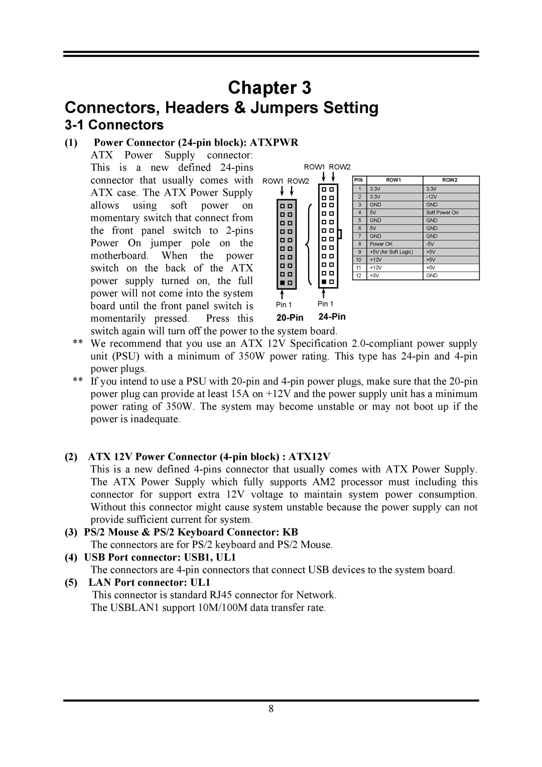
(1)Power Connector
This is a new defined |
|
|
| ROW1 ROW2 |
|
| ||||||||||||
connector that | usually comes | with | ROW1 ROW2 |
|
|
|
|
|
|
|
| |||||||
|
|
|
|
| PIN | ROW1 | ROW2 | |||||||||||
ATX case. The ATX Power Supply |
|
|
|
|
|
|
|
| 1 | 3.3V | 3.3V | |||||||
|
|
|
|
|
|
|
| 2 | 3.3V | |||||||||
allows | using | soft | power | on |
|
|
|
|
|
|
|
| 3 | GND | GND | |||
momentary switch that connect from |
|
|
|
|
|
|
|
| 4 | 5V | Soft Power On | |||||||
|
|
|
|
|
|
|
| 5 | GND | GND | ||||||||
the front panel switch to |
|
|
|
|
|
|
| 6 | 5V | GND | ||||||||
Power | On | jumper | pole | on | the |
|
|
|
|
|
|
| 7 | GND | GND | |||
|
|
|
|
|
|
|
| 8 | Power OK | |||||||||
motherboard. |
| When | the | power |
|
|
|
|
|
|
|
| 9 | +5V (for Soft Logic) | +5V | |||
|
|
|
|
|
|
|
|
| 10 | +12V | +5V | |||||||
switch | on the | back | of the | ATX |
|
|
|
|
|
|
|
| 11 | +12V | +5V | |||
power supply turned on, the full |
|
|
|
|
|
|
|
| 12 | +3V | GND | |||||||
|
|
|
|
|
|
|
|
|
|
|
| |||||||
power will not come into the system |
|
|
|
|
|
|
|
|
|
|
|
| ||||||
|
|
|
|
|
|
|
|
|
|
|
| |||||||
board until the front panel switch is | Pin 1 | Pin 1 |
|
| ||||||||||||||
momentarily | pressed. | Press | this |
|
| |||||||||||||
switch again will turn off the power to the system board.
**We recommend that you use an ATX 12V Specification
**If you intend to use a PSU with
(2)ATX 12V Power Connector (4-pin block) : ATX12V
This is a new defined
(3) PS/2 Mouse & PS/2 Keyboard Connector: KB
The connectors are for PS/2 keyboard and PS/2 Mouse.
(4) USB Port connector: USB1, UL1
The connectors are
(5)LAN Port connector: UL1
This connector is standard RJ45 connector for Network.
The USBLAN1 support 10M/100M data transfer rate.
8