SECTION3: FEATURESANDCONTROLS
WARNING: Before operating your machine, carefully readand understand all safety, controls and operating instructions in this Manual,the separateEngine Owner'sManual,and on the decalson the machine. Failureto follow these instructions can result in serious personal injury.
INTRODUCTION
This Section describes the location and function of the controls on your tiller. Re- fer to the following Section, Operationfor detailed operating instructions.
Practice using these controls, with the en- gine shut off, until you understandthe op- eration of the controls and feel confident with each of them.
ENGINE CONTROLS
Referto the engine manufacturer'sEngine Owner'sManual (included in the tiller liter- ature package)to identify the controls on your engine.
IMPORTANT:Thecontrol for stopping the engine is located on the engine.
WHEEL DRIVE PINS
Eachwheel is equippedwith a wheel drive pin (A,
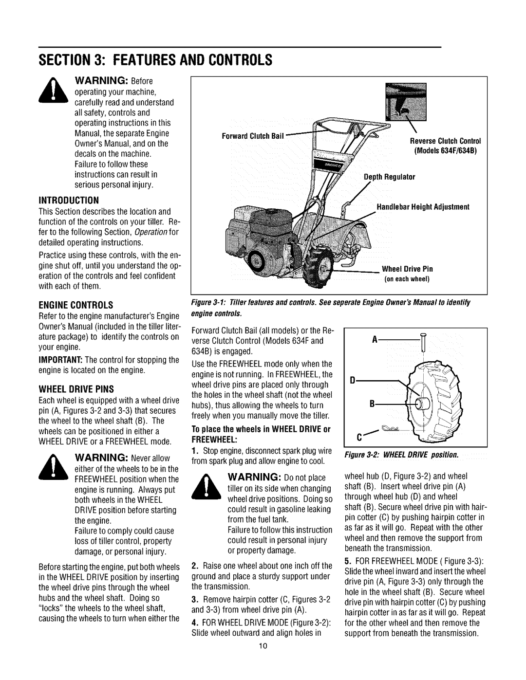
Forward
Reverse ClutchControl
(Models634F/634B)
DepthRegulator
Handlebar Height Adjustment
Wheel Drive Pin (oneachwheel)
Figure3-1: TillerfeaturesandcontrolsSeeseperateEngineOwner'sManualto.identify
enginecontrols.
Forward Clutch Bail (all models) or the Re- verseClutch Control (Models 634F and 634B) is engaged.
Usethe FREEWHEELmode only when the engineis not running. In FREEWHEEL,the wheel drive pins are placed only through the holes in the wheel shaft (not the wheel hubs), thus allowing the wheels to turn freely when you manually movethe tiller.
wheelscan be positioned in either a WHEELDRIVEora FREEWHEELmode.
WARNING: Neverallow either of the wheelsto bein the FREEWHEELposition when the engineis running. Always put both wheelsin the WHEEL DRIVEposition before starting the engine.
Failureto comply could cause loss of tiller control, property damage,or personal injury.
Beforestarting the engine,put both wheels in the WHEELDRIVEposition by inserting the wheel drive pins through the wheel hubs and the wheel shaft. Doing so "locks" the wheels to the wheel shaft, causingthe wheelsto turn when either the
To place the wheels in WHEELDRIVEot
FREEWHEEL:
1.Stop engine,disconnectsparkplugwire from sparkplug andallow engineto cool.
WARNING: Do not place
tiller on its side when changing wheeldrive positions. Doing so
could result in gasoline leaking from the fuel tank.
Failureto follow this instruction could result in personal injury or property damage.
2.Raiseonewheel about one inch off the
ground and placea sturdy support under the transmission.
3.Removehairpin cotter (C,
4.
10
Figure3-2: WHEELDRIVE position.
wheel hub (D, Figure
shaft (B). Securewheel drive pin with hair- pin cotter (C) by pushing hairpin cotter in as far as it will go. Repeatwith the other wheel and then remove the support from beneaththe transmission.
5.FORFREEWHEELMODE(