3 ![]()
3.4.4.1 Removing a Module
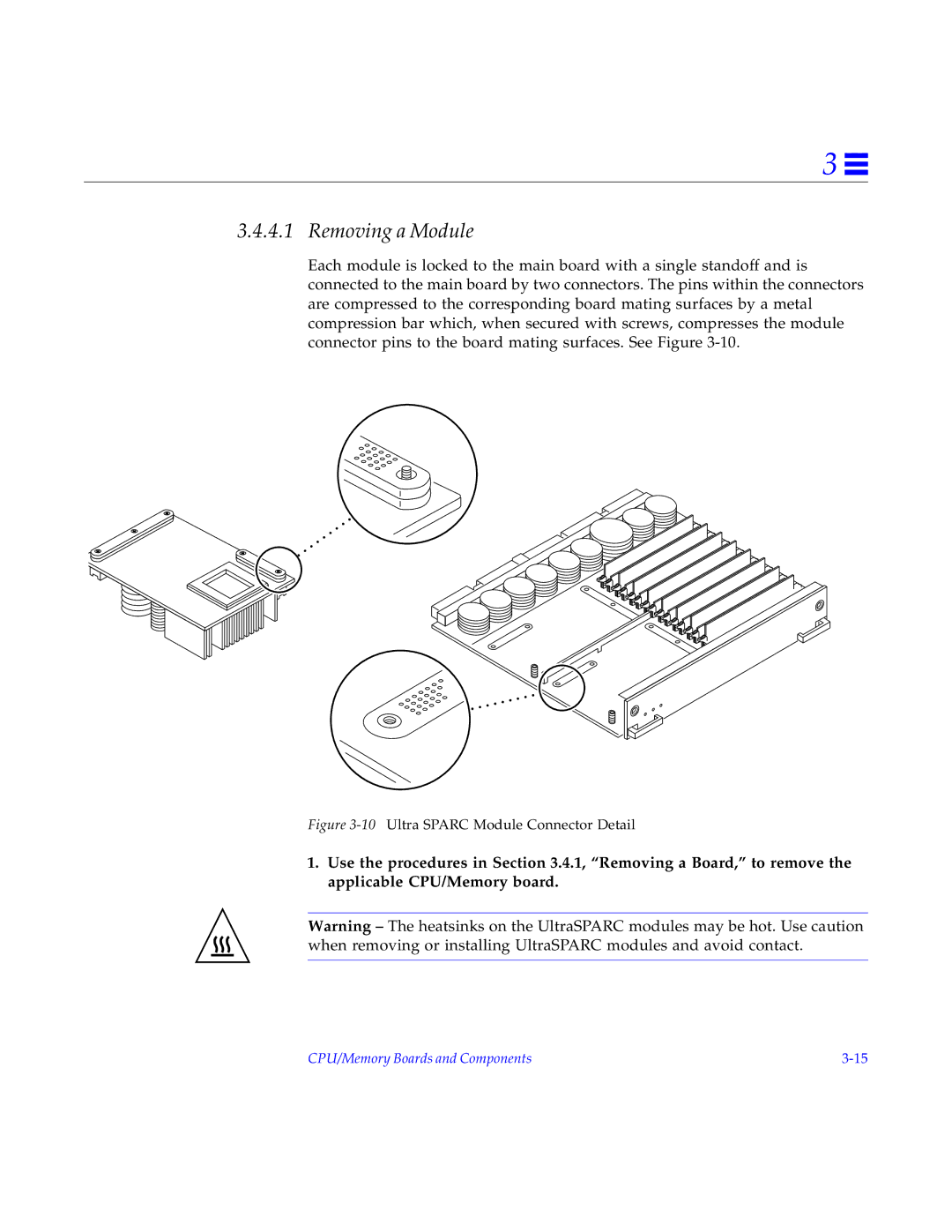
Each module is locked to the main board with a single standoff and is connected to the main board by two connectors. The pins within the connectors are compressed to the corresponding board mating surfaces by a metal compression bar which, when secured with screws, compresses the module connector pins to the board mating surfaces. See Figure
Figure 3-10 Ultra SPARC Module Connector Detail
1.Use the procedures in Section 3.4.1, “Removing a Board,” to remove the applicable CPU/Memory board.
Warning – The heatsinks on the UltraSPARC modules may be hot. Use caution when removing or installing UltraSPARC modules and avoid contact.
CPU/Memory Boards and Components |