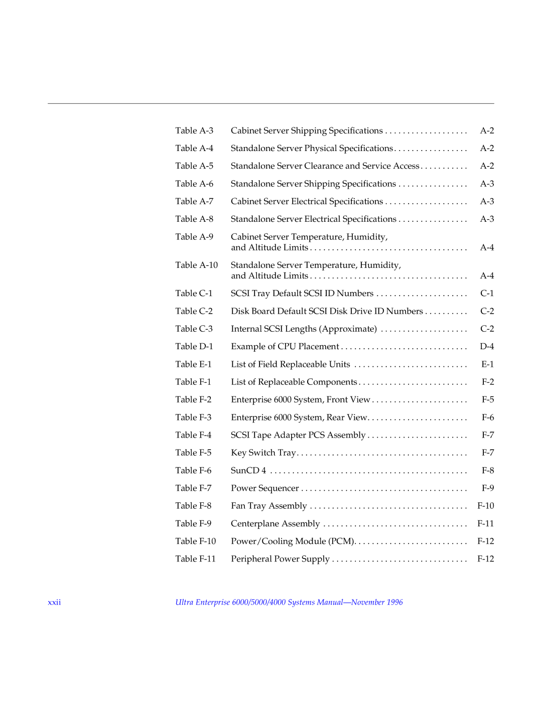
Table | Cabinet Server Shipping Specifications | |
Table | Standalone Server Physical Specifications | |
Table | Standalone Server Clearance and Service Access | |
Table | Standalone Server Shipping Specifications | |
Table | Cabinet Server Electrical Specifications | |
Table | Standalone Server Electrical Specifications | |
Table | Cabinet Server Temperature, Humidity, |
|
| and Altitude Limits | |
Table | Standalone Server Temperature, Humidity, |
|
| and Altitude Limits | |
Table | SCSI Tray Default SCSI ID Numbers | |
Table | Disk Board Default SCSI Disk Drive ID Numbers | |
Table | Internal SCSI Lengths (Approximate) | |
Table | Example of CPU Placement | |
Table | List of Field Replaceable Units | |
Table | List of Replaceable Components | |
Table | Enterprise 6000 System, Front View | |
Table | Enterprise 6000 System, Rear View | |
Table | SCSI Tape Adapter PCS Assembly | |
Table | Key Switch Tray | |
Table | SunCD 4 | |
Table | Power Sequencer | |
Table | Fan Tray Assembly | |
Table | Centerplane Assembly | |
Table | Power/Cooling Module (PCM) | |
Table | Peripheral Power Supply |
xxii | Ultra Enterprise 6000/5000/4000 Systems |
