![]() 12
12
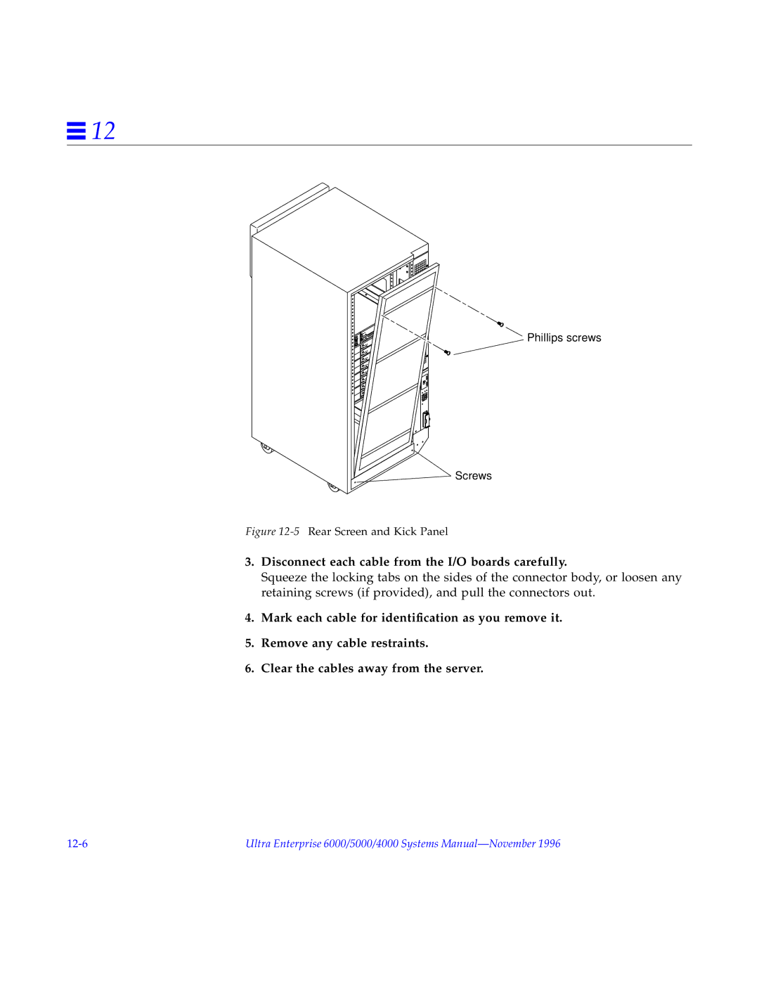
Phillips screws
Screws
Figure 12-5 Rear Screen and Kick Panel
3.Disconnect each cable from the I/O boards carefully.
Squeeze the locking tabs on the sides of the connector body, or loosen any retaining screws (if provided), and pull the connectors out.
4.Mark each cable for identification as you remove it.
5.Remove any cable restraints.
6.Clear the cables away from the server.
Ultra Enterprise 6000/5000/4000 Systems |
