3 ![]()
6.Lock the SIMM in place by pushing both ejector levers into the upright position.
See Figure 3-16.
7.Install the CPU/Memory board and detach the wrist strap. See Section 3.4.2, “Installing a Board.”
8.As you reboot the system, watch for the system banner to verify that the new memory is recognized by the system.
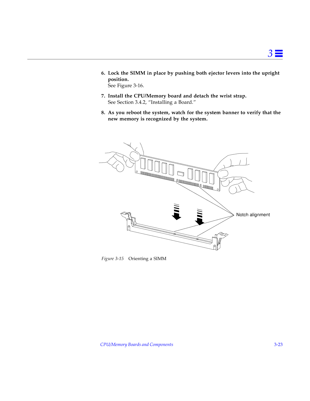
Notch alignment
Figure 3-15 Orienting a SIMM
CPU/Memory Boards and Components |