| Fig. |
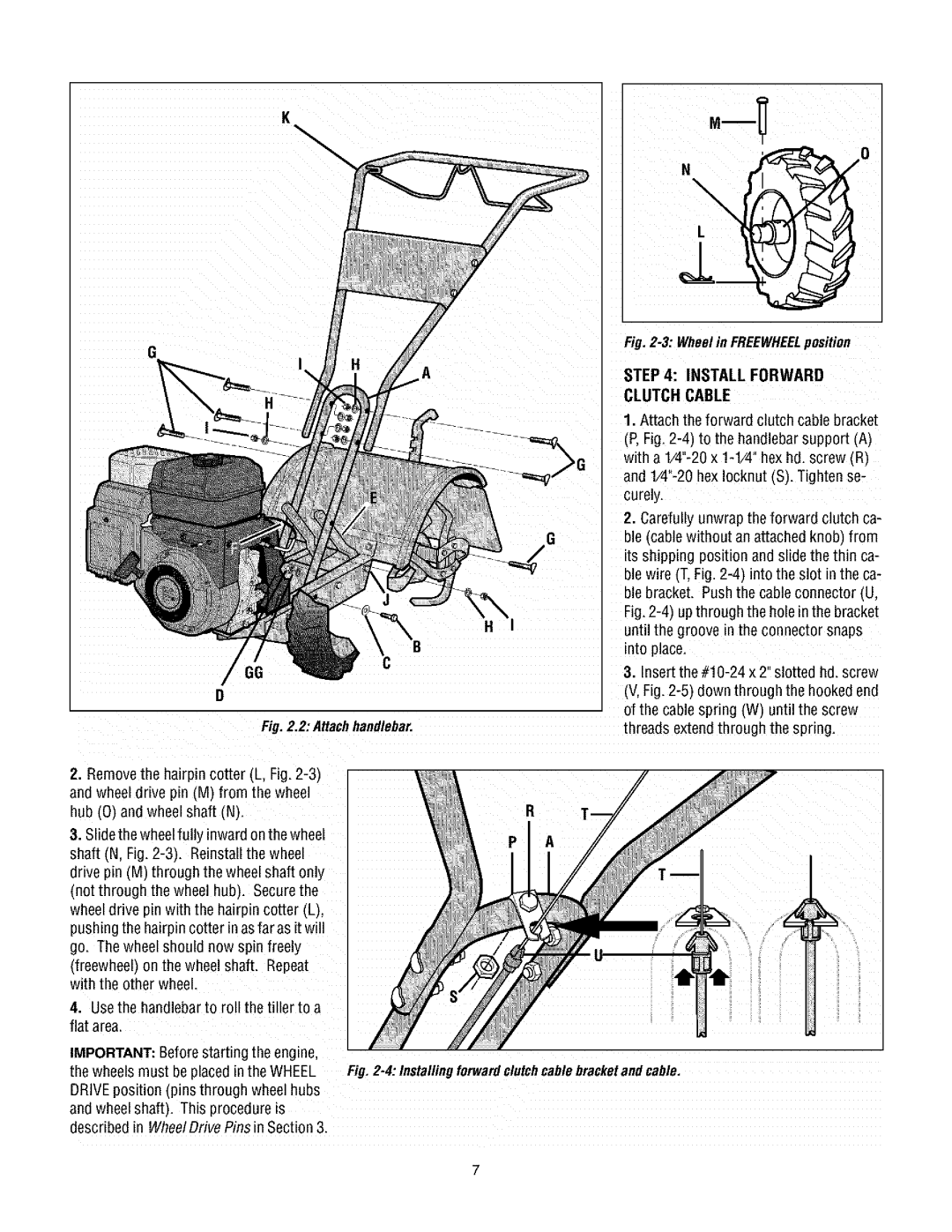
| STEP 4: INSTALL FORWARD |
| CLUTCH CABLE |
| 1. Attach the forward clutch cable bracket |
| (P, Fig. |
| with a |
| and |
| curely. |
| 2. Carefully unwrap the forward clutch ca- |
| ble (cable without anattached knob, from |
| its shipping position and slide the thin ca- |
| ble wire (T. Fig. |
| ble bracket. Push the cable connector (U. |
| Fig. |
| until the groove in the connector snaps |
| into place. |
| 3. Insert the |
| (V, Fig. |
| of the cable spring (W) until the screw |
Fig.2,2: AHachhandlebar, | threads extendthrough the spring. |
2. Removethe hairpin cotter (L, Fig. |
|
and wheel drive pin (M) from the wheel |
|
hub (0) and wheel shaft (N). |
|
3. Slidethe wheelfully inward onthe wheel |
|
shaft (N, Fig. |
|
drive pin (M) through the wheel shaft only |
|
(not through the wheel hub). Securethe |
|
wheel drive pin with the hairpin cotter (L), |
|
pushing the hairpincotter in asfar as it will |
|
go. The wheel should now spin freely |
|
(freewheel) on the wheel shaft. Repeat |
|
with the other wheel. |
|
4. Usethe handlebarto roll the tiller to a |
|
flat area. |
|
IMPORTANT: Before starting the engine,
the wheels must be placedin the WHEEL Fig.2=4:Installingforwardclutchcablebracketandcable. DRIVEposition (pins through wheel hubs
andwheel shaft). This procedure is described in WheelDrive Pins in Section3.