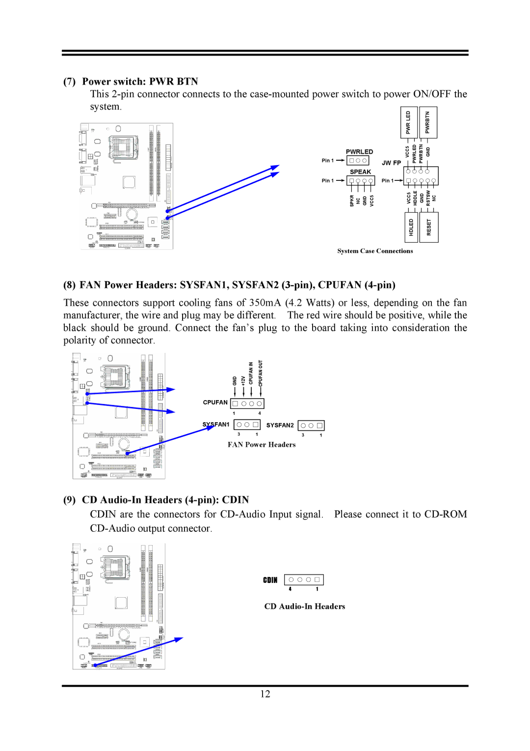
(7) Power switch: PWR BTN
This | |
system. | PWR LED |
| |
PWRLED | VCC5 |
| |
Pin 1 | JW FP |
SPEAK |
|
Pin 1 | Pin 1 |
SPKR NC GND VCC5 | VCC5 |
ON/OFF the
|
| PWRBTN |
PWRLED | PWRBTN | GND |
HDDLE | GND | RSTSW NC |
HDLED
System Case Connections
RESET
(8) FAN Power Headers: SYSFAN1, SYSFAN2 (3-pin), CPUFAN (4-pin)
These connectors support cooling fans of 350mA (4.2 Watts) or less, depending on the fan manufacturer, the wire and plug may be different. The red wire should be positive, while the black should be ground. Connect the fan’s plug to the board taking into consideration the polarity of connector.
GND +12V CPUFAN IN | CPUFAN OUT |
CPUFAN ![]()
![]()
1
SYSFAN1
3
4
SYSFAN2
1 | 3 | 1 |
FAN Power Headers
(9) CD Audio-In Headers (4-pin): CDIN
CDIN are the connectors for
CDIN
41
CD
12