OPERATION | ||
|
|
|
VANTAGE® 300 settings when using the
•Set the MODE Switch to the TOUCH START TIG setting.
•Set the "IDLER" Switch to the "AUTO" position.
•Set the "WELDING TERMINALS" switch to the "REMOTELY CONTROLLED" position. This will keep the "Solid State" contactor open and provide a "cold" electrode until the Amptrol or Arc Start Switch is pressed.
When using the TIG Module, the OUTPUT CONTROL on the VANTAGE® 300 is used to set the maximum range of the CUR- RENT CONTROL on the TIG Module or an Amptrol if connect- ed to the TIG Module.
WIRE WELDING-CV
Connect a wire feeder to the VANTAGE® 300 according to the instructions in INSTALLATION INSTRUCTIONS Section.
The VANTAGE® 300 in the
NOTE: In the
ARC GOUGING
The VANTAGE 300 can be used for arc gouging. For optimal performance, set the MODE switch to ARC GOUGING.
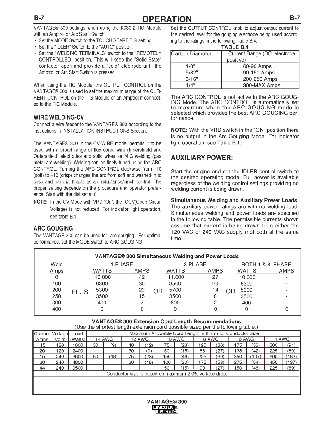
Set the OUTPUT CONTROL knob to adjust output current to the desired level for the gouging electrode being used accord- ing to the ratings in the following Table B.4.
| TAbLE b.4 |
Carbon Diameter | Current Range (DC, electrode |
| positive) |
1/8" | |
5/32" | |
3/16" | |
1/4" |
The ARC CONTROL is not active in the ARC GOUG- ING Mode. The ARC CONTROL is automatically set to maximum when the ARC GOUGING mode is selected which provides the best ARC GOUGING per- formance.
NOTE: With the VRD switch in the “ON” position there is no output in the Arc Gouging Mode. For indicator light operation, see Table B.1.
AUXILIARY POWER:
Start the engine and set the IDLER control switch to the desired operating mode. Full power is available regardless of the welding control settings providing no welding current is being drawn.
Simultaneous Welding and Auxiliary Power Loads The auxiliary power ratings are with no welding load. Simultaneous welding and power loads are specified in the following table. The permissible currents shown assume that current is being drawn from either the 120 VAC or 240 VAC supply (not both at the same time).
|
|
|
|
|
|
|
|
|
|
|
|
|
|
|
|
|
|
|
|
|
|
|
|
|
|
|
|
|
|
|
|
|
|
|
|
|
|
|
|
|
|
|
|
| VANTAGE® 300 Simultaneous Welding and Power Loads |
|
|
|
|
|
|
|
|
| |||||||||||||||||||||
|
| Weld |
|
|
|
|
|
|
|
|
|
|
|
|
|
|
|
|
|
|
|
|
|
|
|
|
|
|
|
|
|
|
|
|
| ||
|
|
|
|
|
|
|
|
|
|
|
|
|
|
|
|
|
|
|
|
|
|
|
|
|
|
|
|
|
|
|
|
|
|
| |||
|
|
|
|
|
|
|
| 1 PHASE |
|
|
|
|
|
|
|
|
| 3 PHASE |
|
|
|
|
|
| BOTH 1 & 3 PHASE |
|
| ||||||||||
|
| Amps |
|
|
|
| WATTS |
| AMPS |
|
|
|
| WATTS |
| AMPS |
|
|
| WATTS |
| AMPS |
|
| |||||||||||||
|
| 0 |
|
|
|
| 10,000 |
| 42 |
|
|
|
|
| 11,000 |
| 27 |
|
|
|
| 10,000 |
| - |
|
|
| ||||||||||
|
| 100 |
|
|
| 8300 |
|
| 35 |
|
|
|
| 8500 |
| 20 |
|
|
| 8300 |
|
| - |
|
|
| |||||||||||
|
| 200 | PLUS | 5300 |
|
| 22 |
|
| OR | 5700 |
| 14 |
| OR | 5300 |
|
| - |
|
|
| |||||||||||||||
|
| 250 |
|
|
| 3500 |
|
| 15 |
|
|
|
| 3500 |
| 8 |
|
|
| 3500 |
|
| - |
|
|
| |||||||||||
|
| 300 |
|
|
| 400 |
|
| 2 |
|
|
|
|
|
| 800 |
| 2 |
|
|
|
|
| 400 |
|
| - |
|
|
| |||||||
|
| 400 |
|
|
| 0 |
|
|
| 0 |
|
|
|
|
|
| 0 |
| 0 |
|
|
|
|
| 0 |
|
| 0 |
|
|
| ||||||
|
|
|
|
|
|
|
|
|
|
|
|
|
|
|
|
|
|
|
|
|
|
|
|
|
|
|
|
|
|
|
|
| |||||
|
|
|
|
|
|
|
|
|
|
|
|
|
|
|
|
|
|
|
|
|
|
|
|
|
|
|
|
|
|
|
|
|
|
|
|
|
|
|
|
|
|
|
|
| VANTAGE® 300 Extension Cord Length Recommendations |
|
|
|
|
|
|
|
|
| |||||||||||||||||||||
|
|
| (Use the shortest length extension cord possible sized per the following table.) |
|
|
|
|
|
| ||||||||||||||||||||||||||||
| Current Voltage | Load |
|
|
|
|
| Maximum Allowable Cord Length in ft. (m) for Conductor Size |
|
|
|
|
|
| |||||||||||||||||||||||
| (Amps) | Volts | (Watts) |
|
| 14 AWG | 12 AWG |
|
|
| 10 AWG | 8 AWG |
|
|
| 6 AWG | 4 AWG | ||||||||||||||||||||
| 15 | 120 | 1800 |
| 30 |
| (9) | 40 |
| (12) |
| 75 |
| (23) | 125 |
| (38) |
| 175 |
| (53) | 300 |
| (91) |
|
| |||||||||||
| 20 | 120 | 2400 |
|
|
|
|
| 30 |
| (9) |
|
| 50 |
| (15) | 88 |
| (27) |
| 138 |
| (42) | 225 |
| (69) |
|
| |||||||||
| 15 | 240 | 3600 |
| 60 |
| (18) | 75 |
| (23) |
| 150 |
| (46) | 225 |
| (69) |
| 350 |
| (107) | 600 |
| (183) |
|
| |||||||||||
| 20 | 240 | 4800 |
|
|
|
|
| 60 |
| (18) |
| 100 |
| (30) | 175 |
| (53) |
| 275 |
| (84) | 450 |
| (137) |
|
| ||||||||||
| 44 | 240 | 9500 |
|
|
|
|
|
|
|
|
|
|
| 50 |
| (15) | 90 |
| (27) |
| 150 |
| (46) | 225 |
| (69) |
|
| ||||||||
|
|
|
|
|
|
|
| Conductor size is based on maximum 2.0% voltage drop. |
|
|
|
|
|
|
|
|
| ||||||||||||||||||||
|
|
|
|
|
|
|
|
|
|
|
|
|
|
|
|
|
|
|
|
|
|
|
|
|
|
|
|
|
|
|
|
|
|
|
|
|
|