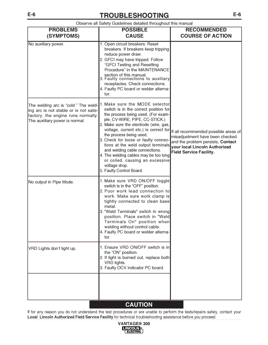
TROUbLESHOOTING | ||
|
|
|
| Observe all Safety Guidelines detailed throughout this manual |
|
PRObLEMS
(SYMPTOMS)
POSSIbLE
CAUSE
RECOMMENDED
COURSE OF ACTION
No auxiliary power. | 1. Open circuit breakers. Reset |
|
| breakers. If breakers keep tripping |
|
| reduce power draw. |
|
| 2. GFCI may have tripped. Follow |
|
| “GFCI Testing and Resetting |
|
| Procedure” in the MAINTENANCE |
|
| section of this manual. |
|
| 3. Faulty connections to auxiliary |
|
| receptacles. Check connections. |
|
| 4. Faulty PC board or welder alterna- |
|
| tor. |
|
|
|
|
The welding arc is “cold.” The weld- | 1. Make sure the MODE selector |
|
ing arc is not stable or is not satis- | switch is in the correct position for |
|
the process being used. (For exam- |
| |
factory. the engine runs normally. |
| |
ple, |
| |
The auxiliary power is normal. |
| |
2. Make sure the electrode (wire, gas, |
| |
|
| |
| voltage, current etc.) is correct for | If all recommended possible areas of |
| the process being used. | misadjustment have been checked |
| 3. Check for loose or faulty connec- | |
| and the problem persists, Contact | |
| tions at the weld output terminals | your local Lincoln Authorized |
| and welding cable connections. | Field Service Facility. |
| 4. The welding cables may be too long | |
| or coiled, causing an excessive |
|
| voltage drop. |
|
| 5. Faulty Control Board. |
|
|
|
|
No output in Pipe Mode. | 1. Make sure VRD ON/OFF toggle |
|
switch is in the “OFF” position. |
| |
|
| |
| 2. Poor work lead connection to |
|
| work. Make sure work clamp is |
|
| tightly connected to clean base |
|
| metal. |
|
| 3. "Weld Terminals" switch in wrong |
|
| position. Place switch in "Weld |
|
| Terminals On" position when |
|
| welding without control cable. |
|
| 4. Faulty PC board or welder alterna- |
|
| tor. |
|
|
|
|
VRD Lights don’t light up. | 1. Ensure VRD ON/OFF switch is in |
|
the “ON” position. |
| |
|
| |
| 2. If light is burned out, replace both |
|
| VRD lights. |
|
| 3. Faulty OCV indicator PC board. |
|
|
|
|
|
|
|
![]() CAUTION
CAUTION
If for any reason you do not understand the test procedures or are unable to perform the tests/repairs safely, contact your Local Lincoln Authorized Field Service Facility for technical troubleshooting assistance before you proceed.
