Manuals
/
Intel
/
Computer Equipment
/
Computer Accessories
Intel
SR1450
manual
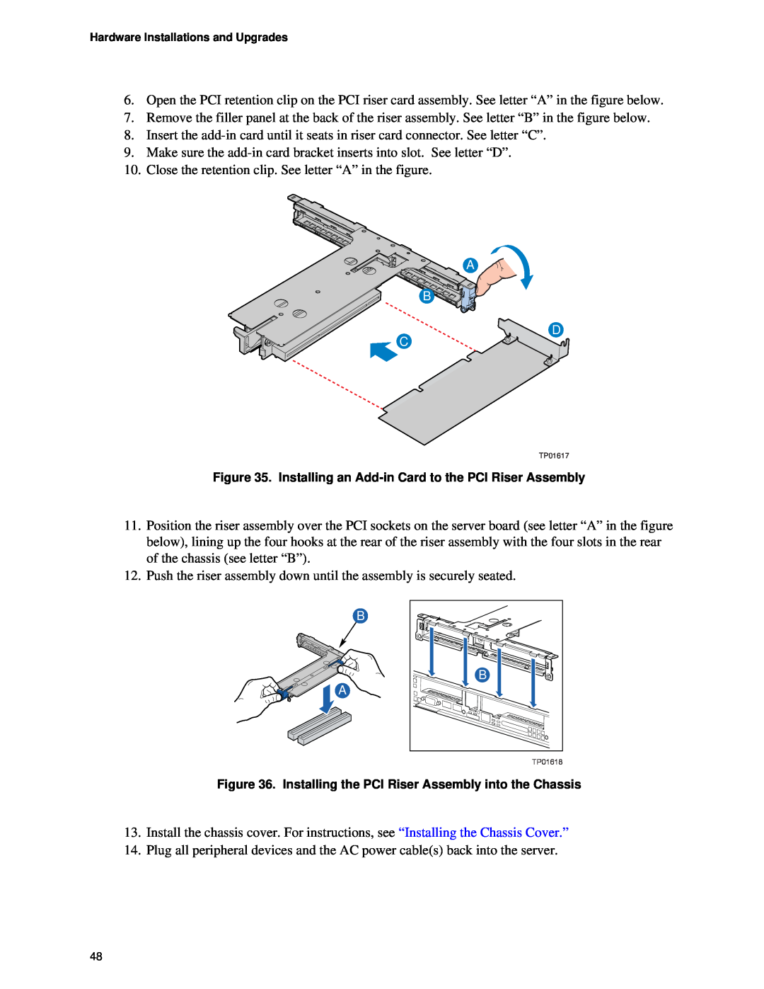
A B D C, TP01617
Models:
SR1450
1
48
87
87
Download
87 pages
48.32 Kb
45
46
47
48
49
50
51
52
Page 48
Image 48
Page 47
Page 49
Page 48
Image 48
Page 47
Page 49
Contents
Intel Server Chassis SR1450 User Guide
Order Number: C95452-002
Disclaimer
Preface
About this Manual
Manual Organization
Product Contents, Order Options, and Accessories
ƒRiser option, choose one •Full-height PCI-Xriser
Additional Information and Software
Safety Information
EMC Testing
Emissions Disclaimer
Intended Uses
Warnings
Safety Cautions
Wichtige Sicherheitshinweise
重要安全指导
Consignes de sécurité
Contents
1 Server Chassis Features
2 Hardware Installations and Upgrades
Intel Server Issue Report Form
Warranty
Equipment Log and Worksheets
Regulatory and Compliance Information
Figures
Tables
1 Server Chassis Features
Figure 1. Intel Server Chassis SR1450
Table 1. Server Chassis Features
Server Chassis Features
Feature
Description
Table 1. Server Chassis Features continued
Component Identification
Internal Components
Standard Control Panel
A B C D E F G H I J K
Callout
Function
Intel Local Control Panel
AB C D E F
N M L K J
I H G
Back Panel Features
Figure 4. Intel Local Control Panel Features
Figure 5. Chassis Back
Peripheral Devices Front Features
Hard Disk Drives
NOTES
Advanced Management Options
Floppy / CD-ROM / DVD-ROMSlimline Carriers
Intel Management Module
Rack-MountedSystems
Front Bezels
2 Hardware Installations and Upgrades
Before You Begin
Tools and Supplies Needed
System References
Removing and Installing the Chassis Cover
Removing the Chassis Cover
Installing the Chassis Cover
Figure 8. Installing the Chassis Cover
Removing and Installing the Front Bezel
Removing the Front Bezel
Removing and Installing the Processor Air Duct
Installing the Front Bezel
Installing the Processor Air Duct
Removing the Processor Air Duct
Figure 13. Removing the Processor Air Duct
Figure 15. Installing the Processor Air Duct
Figure 14. Preparing the Processor Air Duct
TP01597
TP01598
Installing and Removing a Hard Disk Drive
Removing a SATA or SCSI Hot-swapHard Disk Drive
Installing a SATA or SCSI Hot-swapHard Disk Drive
B A B
Intel Server Chassis SR1450 User Guide
Installing a Floppy Drive into Slimline Bay
TP01603
TP01604
Removing a Floppy Drive from the Slimline Bay
TP01606
TP01609
TP01323
C AB
5.Remove cables from the interposer board
Installing or Removing a CD-ROMor DVD-ROMDrive
TP01614
Installing and Removing a PCI Riser Card
Installing a PCI Riser Card
10.Release the blue locking lever
Removing a PCI Riser Card
Installing and Removing a PCI Add-inCard
Installing a PCI Add-inCard
A B D C
TP01617
Removing a PCI Add-inCard
Replacing the Standard Control Panel
TP01619
Replacing the Intel Local Control Panel
8.If using a bezel with the Local Control Panel, change out the LCP plastic front panel on the replacement control panel. If you are not using the optional bezel, make sure the back half of the tray is secured in the “shortened” position
Replacing System Fans
Replacing the Single System PCI Fan
8.Connect the fan into the fan connector
Removing the Power Supply Air Duct
Installing the Power Supply Air Duct
Replacing a Power Supply Fan Module
Figure 42. Removing a Power Supply Fan Module
Replacing the Power Distribution Board
19.Reconnect the power supply fans
A B B
Replacing the Hot-SwapPower Supply
Removing a Hot-SwapPower Supply
Installing a Hot-SwapPower Supply
system or wall outlet
Removing the SATA or SCSI Backplane
Installing the SATA or SCSI Backplane
8.Connect the following cables to the backplane
Technical Reference
Cable Routing
A B E C D
Table 3. SATA Cable Routing Reference
Technical Reference
TP01612
Power Supply Specifications
520-WSingle Power Supply Input Voltages
520-WSingle Power Supply Output Voltages
System Environmental Specifications
Table 5. Environmental Specifications
Equipment Log and Worksheets
Equipment Log
Date Installed
Item
Calculating Power Usage
Worksheet, Calculating DC Power Usage
Current Usage
Table 7. Power Usage Worksheet
Voltage level and total current
Total Watts
V X A = W
Product Safety Compliance
Regulatory and Compliance Information
Product Regulatory Compliance
Product EMC Compliance – Class A Compliance
Certifications / Registrations / Declarations
Product Regulatory Compliance Markings
Electromagnetic Compatibility Notices
FCC USA
Industry Canada ICES-003
Europe CE Declaration of Conformity
English translation of the notice above
VCCI Japan
BSMI Taiwan
Korean RRL Compliance
Regulated Specified Components
Getting Help
World Wide Web
Telephone
Intel Server Issue Report Form
Board / Chassis Information
Date Submitted Company Name Contact Name
Email Address Intel Server Product
Operating System Version Service Pack #
Operating System Information
Peripheral Information
Hard Drive Information
Complete Problem Description
Page
Warranty
Limited Warranty for Intel Chassis Subassembly
Extent of Limited Warranty
Products
Warranty Limitations and Exclusions
Limitations of Liability
How to Obtain Warranty Service
Telephone Support
Returning a Defective Product
Top
Page
Image
Contents