Vig390s Motherboard Manual
Viglen, EMC and the ‘CE’ mark
Vig390s Motherboard Manual
Please note
Material in this manual is subject to change without notice
Trademarks
Copyright and Patents
Contents
System Bios
Technical Information
Glossary
Suggestions
Overview
Introduction
System Board Components
PCI
Back Panel Connectors
O shield
Audio 2/4/6 Channel configurations
Description
Feature Summary
Processor Upgrades
System Processor
Microprocessor Packaging
Second Level Cache
System Memory
Main Memory
Memory Configurations
Memory Channel and Dimm Configuration
Dual Channel Interleaved Mode Configurations
Dual Channel Interleaved Mode Configuration with Two DIMMs
256MB
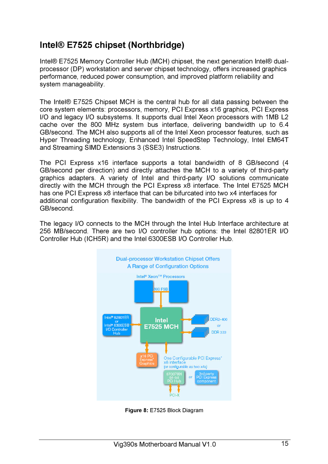
E7525 Block Diagram
Intel E7525 chipset Northbridge
6300 Block Diagram
Intel 6300ESB I/O Controller Southbridge
Vig390s motherboard block diagram
Vig390s Block Diagram
USB Support
IDE Support
Serial ATA Support
Parallel ATA IDE Interfaces
LS-120 Support
Controller
Real-Time Clock, Cmos Sram and Battery
Serial Ports
Floppy Controller
Parallel Port
PS/2 Keyboard and Mouse Interface
Audio Subsystem
Audio Connectors
Front Panel Audio connector
Auxiliary Line In Connector
Atapi Cdrom Audio Connector
RJ-45 LAN Connector LEDs
Features
LAN Subsystem
Hardware Monitoring and Fan Control Asic
Hardware Management Subsystem
Thermal Monitoring
Power Management
Acpi
System States and Power States
Wake-up Devices and Events
Power Connector
Hardware Support
Instantly Available PC Technology
LAN wake Capabilities
Resume on Ring
Wake from USB
PME# Signal Wake-up Support
Wake from PS/2 Devices
System Board Options
Steps to Take to Prevent Static Discharge
Overview of Jumper Settings
System Board Jumper Settings
Jumper Configurations
Clear Cmos Jumper Settings CLRTC1
USB Jumper USBEN1
IEEE1394a Jumper 1394EN1
LAN Jumper LANEN1
Pin Signal name
USB power Jumper USBPW12
Front Panel audio Jumpers Front panel audio
CPU1 FAN power Jumper FMCPU1
Keyboard Power Jumper KBPWR1
CPU2 FAN power Jumper FMCPU2
Motherboard Connectors
Motherboard Connectors
Hard Disk L.E.D. Connector
Reset switch connector
Power L.E.D
Power Switch On/Off
Installing CPU’s
Upgrading the CPU
CPU sockets showing Heatsink clips
CPU sockets
Xeon CPU heatsink
Securing Heatsink through MB
Two Heatsinks fitted through MB
Installing & Removing DDR Sdram In-line Memory Modules
Installing Memory
Removing Memory
Removing DIMMs
Replacing the Clock/CMOS RAM Battery
Removing the Battery
Resetting the System
To do the following Press
Troubleshooting Procedure
Problems Operating Add-in Boards
Problems and Suggestions
What happens What to do
Vig390s Motherboard Manual
Bios Error Messages
Error and Information Messages
Error Message Explanation
Bios Error Messages Explanation
Bios Beep Codes
Beep Codes Beeps Description
What is the BIOS?
Power-on sequence
Bios Upgrades
Introduction
Bios Flash Memory Organisation
Plug and Play PCI Auto-configuration
PCI IDE Support
Address Hex Size Description
Advanced Power Management APM
Primary Cable Secondary Cable Configuration
Plug and Play
Desktop Management Interface DMI
Page
Boot Options
Advanced Configuration and Power Interface Acpi
Language Support
OEM Logo or Scan Area
Bios Setup Access
USB Support
Configuring the Motherboard using Bios Setup
Setting the Processor Speed
Clearing the Passwords
Before You Begin
Bios Setup Program
Setup Menu Screen Description
Setup Key Description
Shows the function keys available for menu screens
Bios Screen layout
Configuration fields
Menu Bar
Menu items
Navigation keys
Legacy Diskette a 44M , 3.5
Main Menu Feature Options Description
44 , 3.5 Default
Main Menu
None
Detected will be displayed
Auto Default
Feature Options Description
Main / Primary P-ATA IDE Master or Slave Sub-menu
Disabled
Enabled
Main / Secondary P-ATA IDE Master or Slave Sub-menu
Secondary P-ATA IDE Master
Udma
Main menu / IDE Configuration Sub-menu
This menu shows the IDE controller configuration
Enhance Mode
ATA Default
Main / System Information Sub-menu
This menu displays system information
This menu is for access to configure advanced features
Power Boot Exit 8Instant Music Configuration
Advanced menu
Main
Advanced / Speech Configuration Sub-menu
This menu allows configuration of speech options
Enabled Default
Speech Post Reporter
Advanced / PCI Express Configuration Sub-menu
Menu below allows the configuration of the PCI-Express LAN
Enabled
Onboard LAN
Advanced / USB Configuration Sub-menu
This menu allows USB controller configuration
All USB Ports Default
Hi Speed
Feature Options Description MPS Revision Default
Advanced / MPS Configuration Sub-menu
MPS Revision
Advanced / CPU Configuration Sub-menu
This manus configures the CPU settings
Enable Default
Auto CPU Lock Free
This menu allows the configuration of chipset features
Automatic Default
8Northbridge Configuration
Advanced / Chipset Sub-menu
Advanced / Northbridge Configuration Sub-menu
This menu configures Northbridge options
Disabled Default
Memory Remap Feature
Advanced / Southbridge configuration Sub-menu
This menu allows the configuration of Southbridge options
Auto Default Onboard audio configuration
Onboard AC’97 Audio Auto
Advanced / Onboard Device Configuration Sub-menu
This menu configures the serial, parallel and game port
3F8/IRQ4 Default
2F8/IRQ3 Default
IRQ7 Default
Normal Default
200/300 200/330 208/300 208/330
This menu allows advanced configuration of PCI BUS
Reserved Memory Size Disabled
Advanced / PCI PnP Sub-menu
Plug And Play O/S
Yes Default
No Default
PCI Device
Power Menu
This menu configures power management
Power Menu Feature Options Description
S3 only Default
Power / APM Configuration Sub-menu
This menu allows the configuration of APM features
Suspended Default
Power Management/APM Enabled
50% Default
On/Off Default
Power Off
To 31 and Every
00 to
Power / Hardware Monitor Sub-menu
This menu configures and shows hardware monitor features
??oC/???oF
????RPM
?.???V Default
Boot Menu
This menu configures boot options
Boot Menu Feature Options Description
Main Advanced Power
Boot / Boot device Priority Sub-menu
This menu configures boot device priority
MBA V7.6.6 Slot 0200Default
Optical drive DetectedDefault
1st CD-ROM
Boot / Hard Drives Sub-menu
This menu allows the HDD boot order to be configured
1st HDD
2nd HDD
This menu sets Bios boot options
Boot / Boot Setting Configuration Sub-menu
On Default
Boot / Security Settings Sub-menu
Not Installed
Full Access
Change Supervisor Password
Setup default
Vig390s Motherboard Manual 100
This menu gives the Bios utility exit options
Exit Menu Feature Options Description
Main Advanced Power Boot
Exit menu
Upgrading the Bios
Preparing for the Upgrade
This chapter describes how to upgrade the Bios
Obtaining the Upgrade Utility
Step TWO Creating a Bootable Floppy Diskette
Step Three Creating the Bios Upgrade Floppy Diskette
Vig390s-BIOS.zip
Upgrading the Bios
An example is shown below of Bios upgrade utility running
Bios Upgrading
Technical Information
Enhanced IDE
Operating Systems and Hard Drives
Vig390s Motherboard Manual 107
Connector Signal Details
Pin
Vig390s Motherboard Manual 108
Fdedin
Vig390s Motherboard Manual 109
Power Supply Connector
Vig390s Motherboard Manual 110
Vig390s Motherboard Manual 111
Vig390s Motherboard Manual 112
Idsel
Motherboard Resources
Vig390s Motherboard Manual 113
Address Range Address Range hex Size Description Decimal
DMA Channel Number Data Width System Resource
Vig390s Motherboard Manual 114
PCI expansion slot 4 J4B1
Bus Device Function Number hex Description
Temperature
Temperature Specification
Other Information
Reliability
Default
Advanced Dynamic Execution
Advance Transfer Cache Level 2 Advance Transfer Cache
Driver
Enhanced Floating Point and Multimedia Unit
Execution Trace Cache Level 1 Execution Trace Cache
Hercules
Hyper-Pipelined Technology
PCI Peripheral Component Interconnect
Internet Streaming Simd Extensions
PCI-Express
Rapid Execution Engine
ATA Serial ATA
Shadow Memory
SSE Streaming Simd Extensions
Vig390s Motherboard Manual 120
Suggestions
Vig390s Motherboard Manual 122