Vig390s specifications
The Intel Vig390s is a sophisticated system-on-chip (SoC) designed for a variety of applications, particularly in the fields of IoT (Internet of Things), industrial automation, and embedded systems. As a versatile processor, it combines high performance with energy efficiency, making it suitable for resource-constrained environments.One of the key features of the Intel Vig390s is its multi-core architecture, which facilitates parallel processing capabilities. This design allows the chip to handle multiple tasks simultaneously, optimizing performance in data-intensive applications. The chip typically incorporates up to four custom cores that operate at impressive clock speeds, ensuring swift processing in complex and demanding workloads.
In terms of graphics capabilities, the Vig390s boasts integrated Intel HD Graphics, providing enhanced visual performance without the need for additional discrete graphics units. This feature is particularly beneficial for applications requiring graphical interfaces, such as smart displays and human-machine interfaces (HMIs), where visual clarity and responsiveness are crucial.
Another notable characteristic of the Vig390s is its support for various connectivity options. The SoC includes integrated networking capabilities, such as Ethernet and Wi-Fi support, enabling seamless communication between devices in an IoT ecosystem. This connectivity enhances the chip's utility in smart factory environments, where real-time data exchange is essential for operational efficiency.
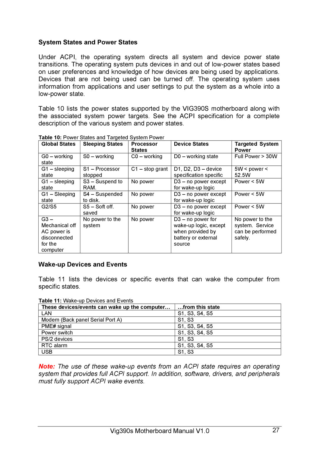
Additionally, the Intel Vig390s is built on advanced manufacturing processes, which not only improves performance but also reduces power consumption. This efficiency is vital for embedded systems that often operate in remote or energy-sensitive environments. The chip has integrated power management features that dynamically adjust performance levels based on workload, thereby extending battery life in portable applications.
The architecture of the Vig390s is also equipped with robust security features, including hardware-based security measures that help protect sensitive data. This capability is increasingly important in an era where cybersecurity threats are prevalent.
With scalability in mind, Intel designed the Vig390s to support a range of operating systems, making it flexible for developers looking to deploy applications across various platforms. Its compatibility with major IoT frameworks enhances its appeal in diverse use cases.
In summary, the Intel Vig390s distinguishes itself with its powerful multi-core processing, integrated graphics, extensive connectivity options, energy efficiency, and security features, making it an ideal choice for modern IoT and embedded applications.
