Lincoln Electric SVM132-A service manual Power Source Connection Diagrams

Models: SVM132-A

1 99
Download 99 pages 19.61 Kb
Page 11
Image 11

Return to Section TOC

Return to Section TOC

Return to Section TOC

Return to Section TOC

Return to Master TOC

Return to Master TOC

Return to Master TOC

Return to Master TOC

A-5

INSTALLATION

A-5


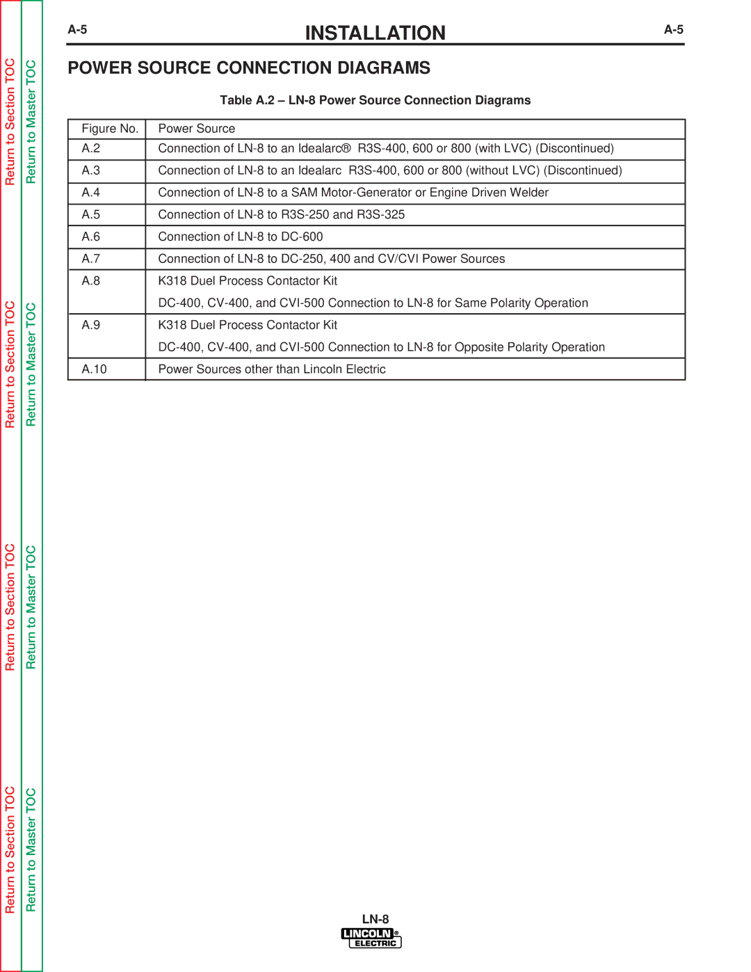
POWER SOURCE CONNECTION DIAGRAMS


Table A.2 – LN-8 Power Source Connection Diagrams


Figure No.

Power Source


A.2

Connection of LN-8 to an Idealarc® R3S-400, 600 or 800 (with LVC) (Discontinued)


A.3

Connection of LN-8 to an Idealarc R3S-400, 600 or 800 (without LVC) (Discontinued)


A.4

Connection of LN-8 to a SAM Motor-Generator or Engine Driven Welder


A.5

Connection of LN-8 to R3S-250 and R3S-325


A.6

Connection of LN-8 to DC-600


A.7

Connection of LN-8 to DC-250, 400 and CV/CVI Power Sources


A.8

K318 Duel Process Contactor Kit


DC-400, CV-400, and CVI-500 Connection to LN-8 for Same Polarity Operation


A.9

K318 Duel Process Contactor Kit


DC-400, CV-400, and CVI-500 Connection to LN-8 for Opposite Polarity Operation


A.10

Power Sources other than Lincoln Electric


LN-8

Page 11
Image 11
Lincoln Electric SVM132-A service manual Table A.2 LN-8 Power Source Connection Diagrams