Return to Section TOC
Return to Master TOC
TROUBLESHOOTING AND REPAIR | ||
|
| |
|
|
|
TRIGGER TRANSFORMER REPLACEMENT (continued)
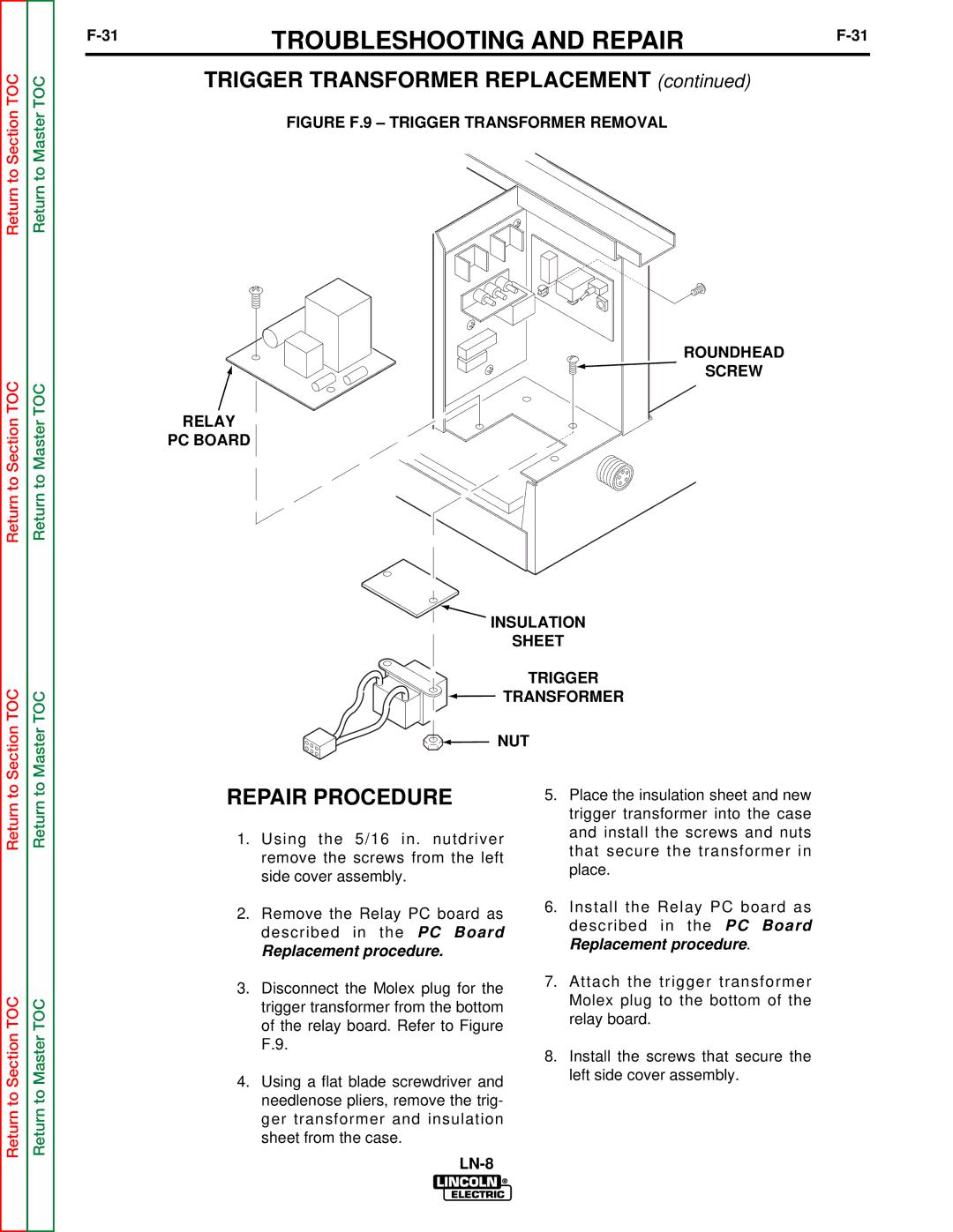
FIGURE F.9 – TRIGGER TRANSFORMER REMOVAL
Return to Section TOC
Return to Master TOC
RELAY
PC BOARD
ROUNDHEAD |
SCREW |
Section TOC
Master TOC
INSULATION
SHEET
TRIGGER
TRANSFORMER
NUT
Return to
Return to Section TOC
Return to
Return to Master TOC
REPAIR PROCEDURE
1.Using the 5/16 in. nutdriver remove the screws from the left side cover assembly.
2.Remove the Relay PC board as described in the PC Board
Replacement procedure.
3.Disconnect the Molex plug for the trigger transformer from the bottom of the relay board. Refer to Figure F.9.
4.Using a flat blade screwdriver and needlenose pliers, remove the trig- ger transformer and insulation sheet from the case.
5.Place the insulation sheet and new trigger transformer into the case and install the screws and nuts that secure the transformer in place.
6.Install the Relay PC board as described in the PC Board Replacement procedure.
7.Attach the trigger transformer Molex plug to the bottom of the relay board.
8.Install the screws that secure the left side cover assembly.