Return to Section TOC
Return to Section TOC
Section TOC
Return to Master TOC
Return to Master TOC
Master TOC
TROUBLESHOOTING AND REPAIR | ||
|
| |
|
|
|
1CR RELAY TEST (continued)
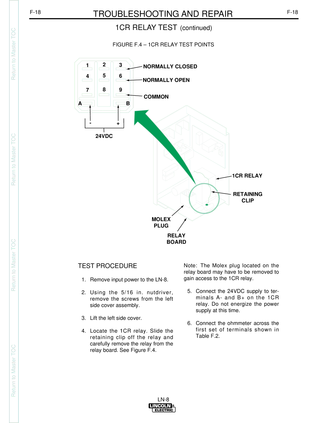
FIGURE F.4 – 1CR RELAY TEST POINTS
1 | 2 | 3 | NORMALLY CLOSED |
4 | 5 | 6 | NORMALLY OPEN |
|
|
|
7 8 9
 COMMON
AB
-+
24VDC
![]() 1CR RELAY
1CR RELAY
 RETAINING
CLIP
MOLEX
PLUG
RELAY
BOARD
Return to
Return to Section TOC
Return to
Return to Master TOC
TEST PROCEDURE
1.Remove input power to the
2.Using the 5/16 in. nutdriver, remove the screws from the left side cover assembly.
3.Lift the left side cover.
4.Locate the 1CR relay. Slide the retaining clip off the relay and carefully remove the relay from the relay board. See Figure F.4.
Note: The Molex plug located on the relay board may have to be removed to gain access to the 1CR relay.
5.Connect the 24VDC supply to ter- minals A- and B+ on the 1CR relay. Do not energize the power supply at this time.
6.Connect the ohmmeter across the first set of terminals shown in
Table F.2.