Return to Section TOC
Return to Section TOC
Return to Master TOC
Return to Master TOC
TROUBLESHOOTING AND REPAIR | |
|
POTENTIOMETER REPLACEMENT (continued)
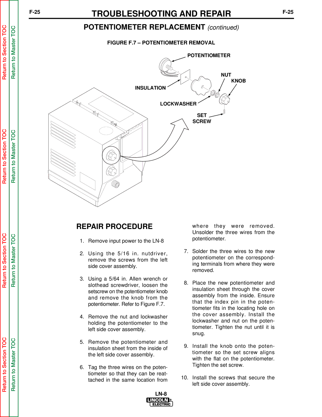
FIGURE F.7 – POTENTIOMETER REMOVAL
POTENTIOMETER
NUT
KNOB
INSULATION
LOCKWASHER
SET 
SCREW
Return to Section TOC
Return to Section TOC
Return to Master TOC
Return to Master TOC
REPAIR PROCEDURE
1.Remove input power to the
2.Using the 5/16 in. nutdriver, remove the screws from the left side cover assembly.
3.Using a 5/64 in. Allen wrench or slothead screwdriver, loosen the setscrew on the potentiometer knob and remove the knob from the potentiometer. Refer to Figure F.7.
4.Remove the nut and lockwasher holding the potentiometer to the left side cover assembly.
5.Remove the potentiometer and insulation sheet from the inside of the left side cover assembly.
6.Tag the three wires on the poten- tiometer so that they can be reat- tached in the same location from
where they were removed. Unsolder the three wires from the potentiometer.
7.Solder the three wires to the new potentiometer on the correspond- ing terminals from where they were removed.
8.Place the new potentiometer and insulation sheet through the cover assembly from the inside. Ensure that the index pin in the poten- tiometer fits in the locating hole on the cover assembly. Install the lockwasher and nut on the poten- tiometer. Tighten the nut until it is snug.
9.Install the knob onto the poten- tiometer so the set screw aligns with the flat on the potentiometer. Tighten the set screw.
10.Install the screws that secure the left side cover assembly.