Return to Section TOC
Return to Master TOC
TROUBLESHOOTING AND REPAIR | ||
|
| |
|
|
|
DRIVE MOTOR TEST (continued)
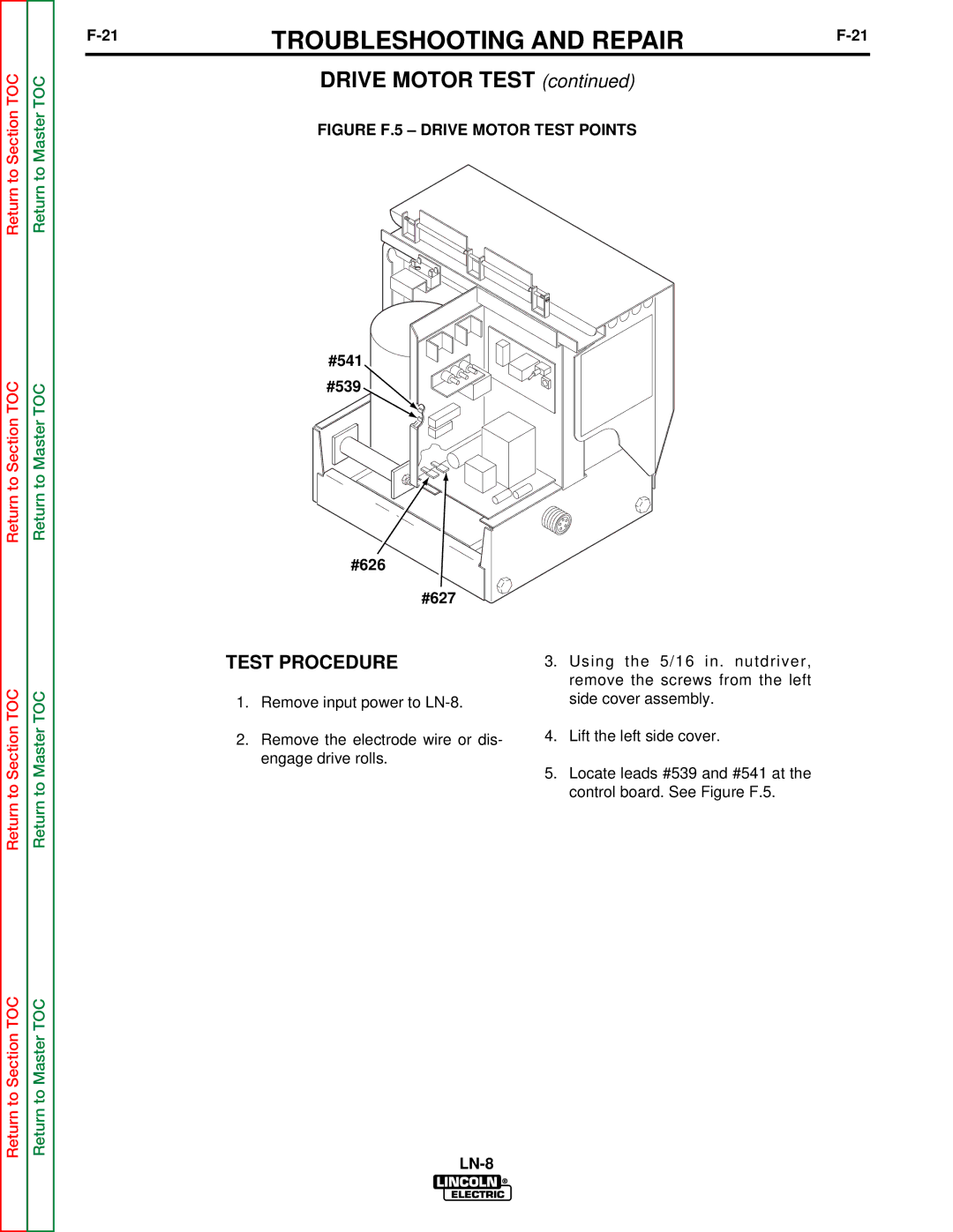
FIGURE F.5 – DRIVE MOTOR TEST POINTS
Return to Section TOC
Return to Section TOC
Return to Master TOC
Return to Master TOC
#541
#539 ![]()
#626
#627
TEST PROCEDURE
1.Remove input power to
2.Remove the electrode wire or dis- engage drive rolls.
3.Using the 5/16 in. nutdriver, remove the screws from the left side cover assembly.
4.Lift the left side cover.
5.Locate leads #539 and #541 at the control board. See Figure F.5.
Return to Section TOC
Return to Master TOC
