Return to Section TOC
Return to Master TOC
TROUBLESHOOTING AND REPAIR | ||
|
| |
|
|
|
PC BOARD REPLACEMENT (continued)
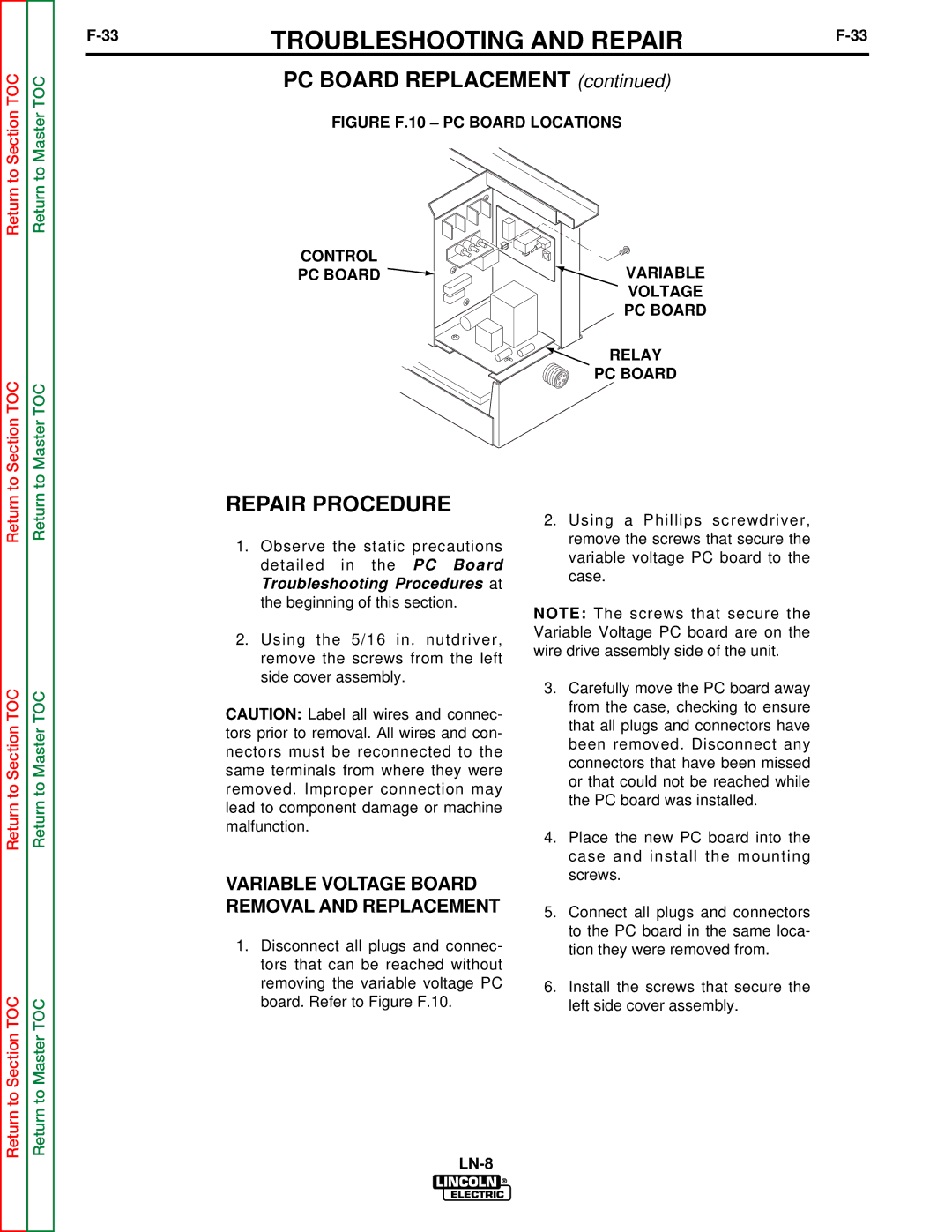
FIGURE F.10 – PC BOARD LOCATIONS
to Section TOC
to Master TOC
CONTROL
PC BOARD 
 VARIABLE VOLTAGE PC BOARD
 RELAY PC BOARD
Return
Return to Section TOC
Return to Section TOC
Return
Return to Master TOC
Return to Master TOC
REPAIR PROCEDURE
1.Observe the static precautions detailed in the PC Board Troubleshooting Procedures at the beginning of this section.
2.Using the 5/16 in. nutdriver, remove the screws from the left side cover assembly.
CAUTION: Label all wires and connec- tors prior to removal. All wires and con- nectors must be reconnected to the same terminals from where they were removed. Improper connection may lead to component damage or machine malfunction.
VARIABLE VOLTAGE BOARD REMOVAL AND REPLACEMENT
1.Disconnect all plugs and connec- tors that can be reached without removing the variable voltage PC board. Refer to Figure F.10.
2.Using a Phillips screwdriver, remove the screws that secure the variable voltage PC board to the case.
NOTE: The screws that secure the Variable Voltage PC board are on the wire drive assembly side of the unit.
3.Carefully move the PC board away from the case, checking to ensure that all plugs and connectors have been removed. Disconnect any connectors that have been missed or that could not be reached while the PC board was installed.
4.Place the new PC board into the case and install the mounting screws.
5.Connect all plugs and connectors to the PC board in the same loca- tion they were removed from.
6.Install the screws that secure the left side cover assembly.