Return to Section TOC
Return to Section TOC
Return to Section TOC
Return to Master TOC
Return to Master TOC
Return to Master TOC
TROUBLESHOOTING AND REPAIR | ||
|
| |
|
|
|
WIRE DRIVE ASSEMBLY AND COMPONENT REPLACEMENT (continued)
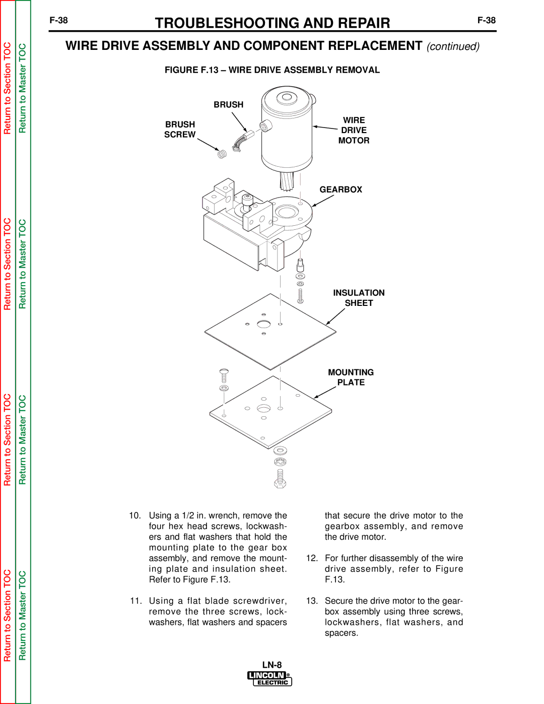
FIGURE F.13 – WIRE DRIVE ASSEMBLY REMOVAL
| BRUSH | |
BRUSH | WIRE | |
DRIVE | ||
SCREW | ||
MOTOR | ||
|
GEARBOX
INSULATION
SHEET
MOUNTING
PLATE
Return to Section TOC
Return to Master TOC
10.Using a 1/2 in. wrench, remove the four hex head screws, lockwash- ers and flat washers that hold the mounting plate to the gear box assembly, and remove the mount- ing plate and insulation sheet. Refer to Figure F.13.
11.Using a flat blade screwdriver, remove the three screws, lock- washers, flat washers and spacers
that secure the drive motor to the gearbox assembly, and remove the drive motor.
12.For further disassembly of the wire drive assembly, refer to Figure F.13.
13.Secure the drive motor to the gear- box assembly using three screws, lockwashers, flat washers, and spacers.
