Return to Section TOC
Return to Master TOC
TROUBLESHOOTING AND REPAIR | ||
|
| |
|
|
|
WIRE DRIVE ASSEMBLY AND COMPONENT REPLACEMENT (continued)
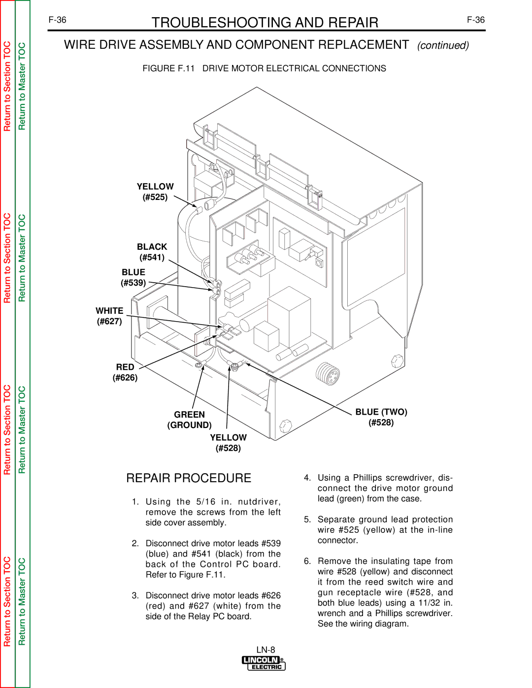
FIGURE F.11 – DRIVE MOTOR ELECTRICAL CONNECTIONS
Return to Section TOC
Return to Section TOC
Return to Section TOC
Return to Master TOC
Return to Master TOC
Return to Master TOC
YELLOW (#525) ![]()
BLACK
(#541)
BLUE (#539) ![]()
WHITE
(#627)
RED
(#626)
GREEN
(GROUND)
YELLOW
(#528)
REPAIR PROCEDURE
1.Using the 5/16 in. nutdriver, remove the screws from the left side cover assembly.
2.Disconnect drive motor leads #539 (blue) and #541 (black) from the back of the Control PC board. Refer to Figure F.11.
3.Disconnect drive motor leads #626 (red) and #627 (white) from the side of the Relay PC board.
BLUE (TWO)
(#528)
4.Using a Phillips screwdriver, dis- connect the drive motor ground lead (green) from the case.
5.Separate ground lead protection wire #525 (yellow) at the
6.Remove the insulating tape from wire #528 (yellow) and disconnect it from the reed switch wire and gun receptacle wire (#528, and both blue leads) using a 11/32 in. wrench and a Phillips screwdriver. See the wiring diagram.