Return to Section TOC
Return to Section TOC
Return to Section TOC
Return to Section TOC
Return to Master TOC
Return to Master TOC
Return to Master TOC
Return to Master TOC
| TROUBLESHOOTING AND REPAIR |
| |||||
|
|
|
| ||||
|
|
|
|
|
|
|
|
|
|
| INTERNAL VOLTAGE TEST (continued) |
|
| ||
|
|
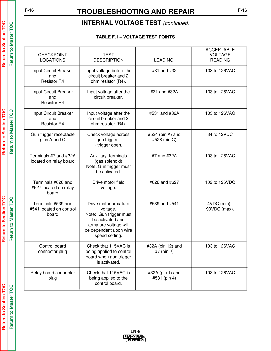
| TABLE F.1 – VOLTAGE TEST POINTS |
|
| ||
|
|
|
|
|
|
|
|
|
|
|
|
|
| ACCEPTABLE |
|
CHECKPOINT |
| TEST |
|
| VOLTAGE |
| |
| LOCATIONS |
| DESCRIPTION | LEAD NO. |
| READING |
|
|
|
|
|
|
|
| |
Input Circuit Breaker |
| Input voltage before the | #31 and #32 |
| 103 to 126VAC |
| |
| and |
| circuit breaker and 2 |
|
|
|
|
| Resistor R4 |
| ohm resistor (R4). |
|
|
|
|
|
|
|
|
|
|
| |
Input Circuit Breaker |
| Input voltage after the | #31 and #32A |
| 103 to 126VAC |
| |
| and |
| circuit breaker. |
|
|
|
|
| Resistor R4 |
|
|
|
|
|
|
|
|
|
|
|
|
| |
Input Circuit Breaker |
| Input voltage after the | #531 and #32A |
| 103 to 126VAC |
| |
| and |
| circuit breaker and 2 |
|
|
|
|
| Resistor R4 |
| ohm resistor (R4). |
|
|
|
|
|
|
|
|
|
|
| |
Gun trigger receptacle |
| Check voltage across | #524 (pin A) and |
| 34 to 42VDC |
| |
| pins A and C |
| gun trigger - | #528 (pin C) |
|
|
|
|
|
| - trigger open. |
|
|
|
|
|
|
|
|
|
|
| |
Terminals #7 and #32A |
| Auxiliary terminals | #7 and #32A |
| 103 to 126VAC |
| |
located on relay board |
| (gas solenoid) |
|
|
|
| |
|
|
| Note: Gun trigger must |
|
|
|
|
|
|
| be activated. |
|
|
|
|
|
|
|
|
|
|
| |
Terminals #626 and |
| Drive motor field | #626 and #627 |
| 102 to 125VDC |
| |
#627 located on relay |
| voltage. |
|
|
|
| |
| board |
|
|
|
|
|
|
|
|
|
|
|
|
| |
Terminals #539 and |
| Drive motor armature | #539 and #541 |
| 4VDC (min) - |
| |
#541 located on control |
| voltage. |
|
| 90VDC (max). |
| |
| board |
| Note: Gun trigger must |
|
|
|
|
|
|
| be activated and |
|
|
|
|
|
|
| armature voltage will |
|
|
|
|
|
|
| be dependent upon wire |
|
|
|
|
|
|
| speed setting. |
|
|
|
|
|
|
|
|
|
|
|
|
| Control board |
| Check that 115VAC is | #32A (pin 12) and |
| 103 to 126VAC |
|
connector plug |
| being applied to control | #7 (pin 2) |
|
|
| |
|
|
| board when gun trigger |
|
|
|
|
|
|
| is activated. |
|
|
|
|
|
|
|
|
|
|
| |
Relay board connector |
| Check that 115VAC is | #32A (pin 1) and |
| 103 to 126VAC |
| |
| plug |
| being applied to the | #531 (pin 4) |
|
|
|
|
|
| control board. |
|
|
|
|
|
|
|
|
|
|
|
|